Week - 4
1)Implement control logic of a "Washing machine" using Stateflow:
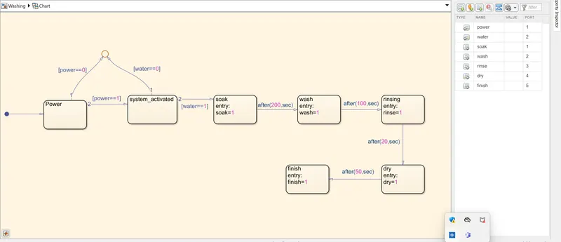
Implementation of control logic chart for Washing Machine using stateflow
Steps:
- Start simulink and create a blank model.
- Create a chart block for defining the stateflow as per the given conditions.
- I used junction and states in the chart as per conditions.
- Inside it, the circular junction is to terminated the signal flow and return a null value.
- If power supply is off i.e. 0, means the process is terminated at the junction else 1 , the process is forwarded.
- If water supply is off i.e. 0, the process is terminated at the junction else 1, the process is forward.
- After, Soak block be activated and action takes place.
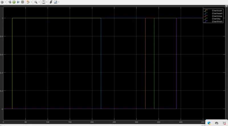
- After 200 sec of Soaking, Wash block be activated and washing action takes place.
- After 100 sec of washing, Rinse block be activated and rinsing action takes place.
- After 20 sec of rinsing, Dry block be activated and drying action takes place.
- After 50 sec of dry, Finish block be activated and process and exits the chart.
- Define power and water as inputs whereas soak, wash, rinse, dry, finish as Outputs.
- After finishing the control logic run the Stateflow and check the sequence of operation for total of 370 sec.
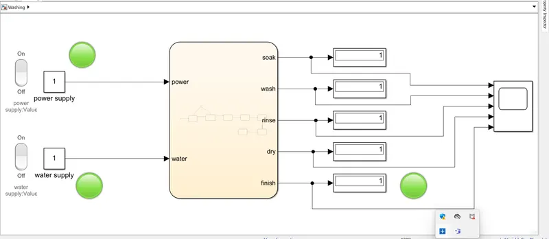
Blocks Used for the simulink model of "Washing machine":
- Chart: Implement control logic with finite state machine.
- Display: This block shows the value of the output.
- Constant: This block generates a real or complex constant value signal. Use to provide a constant signal input.
- Lamp: This block displays a color indicating the value of the signal and can specify pairs of input values and colors to provide the information as I want during the simulation.
- Rocker Switch: This block toggles the value of the connected block parameter between two values during simulation.
Discription:
A Rocker switch is used with a constant to supply the power and as water supply. A lamp is used to indicate the power status and water status like green light shows the power is supplying and Red light shows not supplying and same as water condition.The power status is checked and if it is supply then system is activated and water supply is checked for the soaking and the rinsing process. The timing for each state is as per given inputs like soaking the water for first 200 sec followed by washing time of 100 sec. Rinsing the water for the next 20sec followed by drying time of 50sec. After finish the process the lamp is connected and glow green light.
Outputs :
After completing the simulation of that model of 200 sec the output will be shown below:
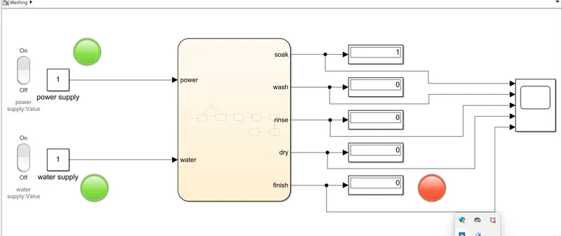
Here, we shown completing the simulation of 200 sec and after simulation the result will be like only soak of water is completed
Again, we run the simulation of the model of 400 sec then all the process be completed and the finish light will be glow with green color shown below:
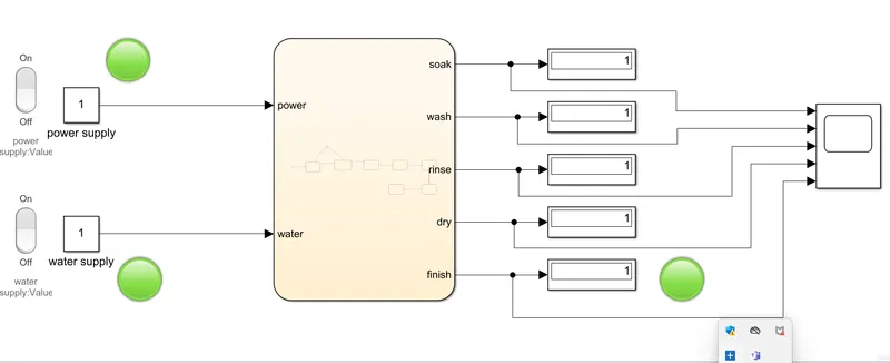
Also see the graph in scope which I connected to each state. In this graph each process should taking time as per given inputs.
2)
Implementation of gearshift logic using stateflow
Aim: Making a simulink chart for the "Gear Shift" logic as per below condition:
Speed Range(km/hr) Gear
0 to 15 1
16 to 25 2
26 to 40 3
41 to 60 4
Above 61 5
Block Used:
- Constant Block
- Slider Block
- Circular Guage Block
- Chart Block
- Display Block
- Lamp Block
Procedure
- First step is to create a stateflow chart in the simulink environment
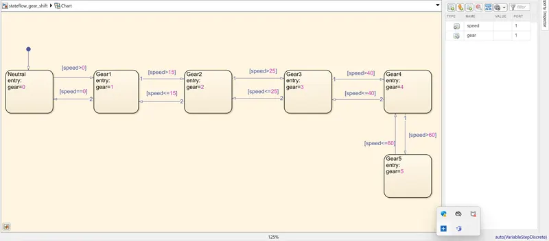
- Then we will create the 5 states for five gear shifts with output arguments as the gear number for the respective states.
- Also give the conditions for the transition from one gear state to other.
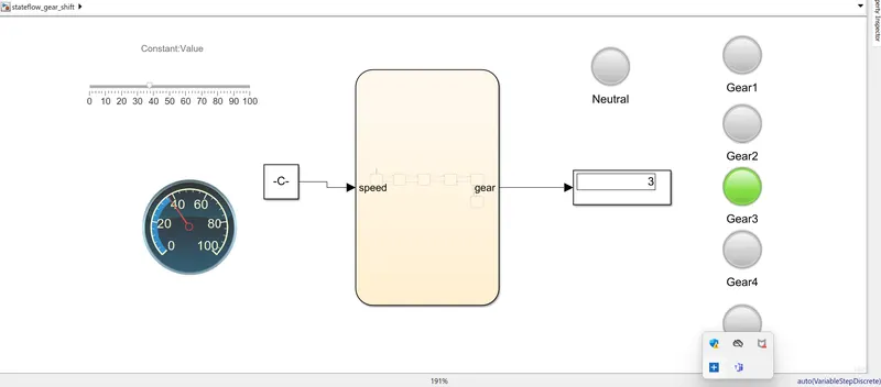
- After that we will define the input and output to the chart. The input has to be made convenient in such a way that the user can provide the input during the simulation. so I made use of a slider gain block along with a constant block.
- We use a circular gauge to show the speed as want to input to the system.
- The output is connected to the display block to displaying which gear number is in the system as our condition.
Simulink Model:
Stateflow Chart:
Output:
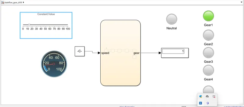
When the speed is below 15 km/hr then gear is in gear 1 as shown below:
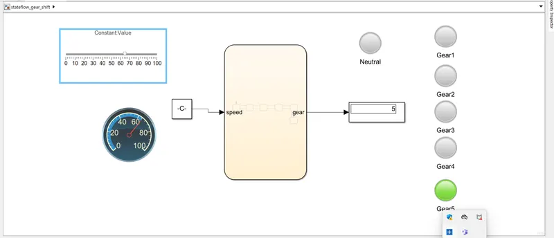
When the speed is above 60 km/hr then the gear display block shows 5 i.e gear 5 and gear 5 lamp glow green color as shown below:
Result:
Simulation of gear shift corresponding to the given speed range have been simulated successfully.