Week - 4
Task-1
AIM
Implement control logic of a “washing machine” using Stateflow
OBJECTIVE
Implement control logic of a “washing machine” using Stateflow as per given sequence
- If the power supply is available, the system gets activated
- If the Water supply is not available, stop the process & indicate through LED
- Soaking time should be 200s followed by Washing time of 100s.
- Then rinsing happens for next 20s & dryer runs for 50s
Model
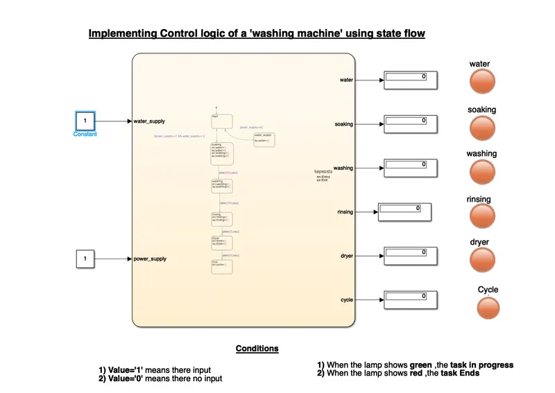
File of the model is attached below
Chart diagram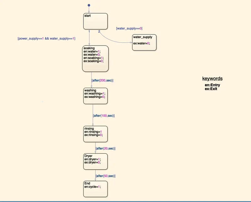
- Washing machine is time based system
- So we have to set time interval for each stages in the cycle
- We set time limits for each stages
- After each time interval system enters the other stage
Parameters
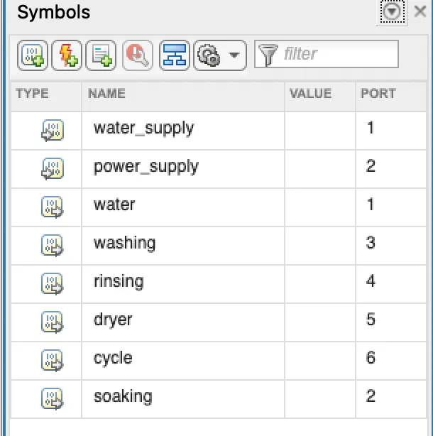
Here we are given water supply and power supply as inputs of the chart
Then we are given water,washing ,rinsing,dryer,cycle,soaking and cycle as output of the chart
Simulation Time parameters
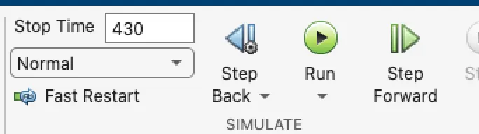
Here our stop time is 430 secs ,this will cover the entire cycle
Condition -1 :Water supply is OFF
Here in this condition we should not provide water supply and check for output
Output
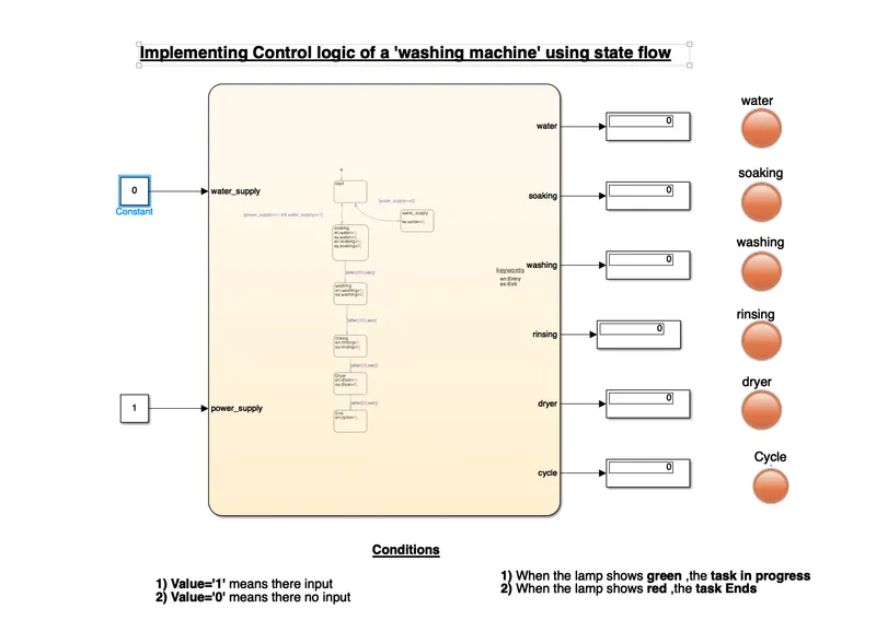
Observations
- When there is not water supply system enters other state and gets off
- System then didn't goes to other states
- Red light indicates off
Condition-2:When water supply is ON
Here in this condition we have to give water supply and check for output
Output
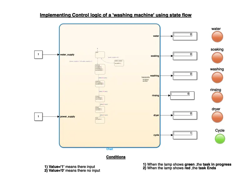
Observations
- Here system gets activated when water supply is given
- System completes the entire cycle
- Green light at last stage indicates that the system completes the cycle
Conclusion
Simulation for washing machine using state flow is done and the results are satisfactory
TASK -2
AIM
Make a Simulink chart for the “Gear shift” logic
OBJECTIVE
Make a Simulink chart for the “Gear shift” logic as per below conditions:
Speed Range(kmph) Gear
0 to 15 1
16 to 25 2
26 to 40 3
41 to 60 4
Above 61 5
MODEL
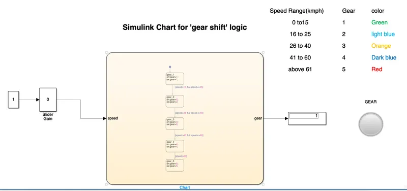
File of the model is attched below
Chart Diagram
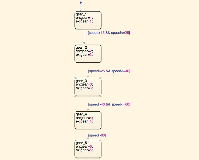
- Here gear is the system
- Gear changes according to speed
- So we have to set speed as input
- Gear changes between fixed speed limits that we sets
- In this chart there is only one variable , that is gear
- Here value of the gear changes according to speed input
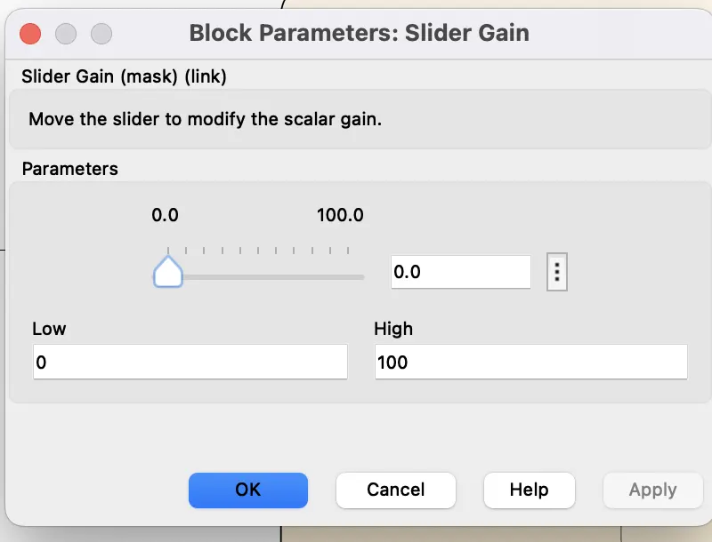
Slider gain
In this model we are connected a slider gain block and constant to change the speed ,this is the input to the system
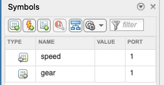
Parameters
Here speed is the input to the chart and gear is the output of chart
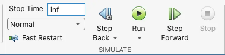
Stop Time
Here stop time is 'inf', so program will run untill we stops
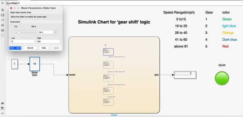
Gear Shifting
Here we changes the gear by changing the speed by means of slider gain
We connected a lamp to the system such that it turns into different color according to the gear
Outputs
Gear -1
Speed range 0 to 15
Input speed 14kmph
color -Green
Observation
As speed changes gear shifted to first gear and so lamp turns green
Gear -2
Speed range 16 to 25
Input speed - 24 kmph
color -Light blue
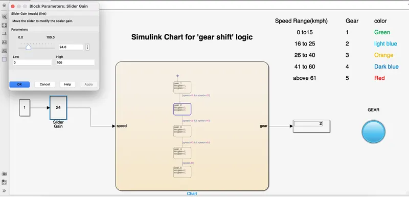
Observation
As speed changes gear shifted to second gear and so lamp turns light blue
Gear-3
Speed range- 26 to 40
Input speed -39 kmph
color -Orange
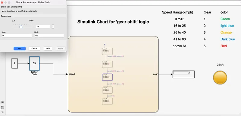
Observation
As speed changes gear shifted to third gear and so lamp turns orange
Gear-4
Speed range 41 to 60
Input speed -59 kmph
color -Dark blue
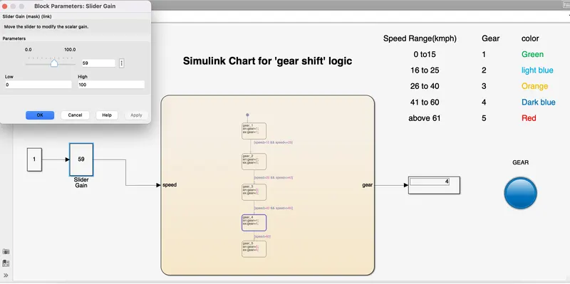
Observation
As speed changes gear shifted to 4th gear and so lamp turns dark blue
Gear -5
Speed range more than 60 kmph
Input speed- 70 kmph
color-Red
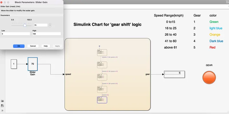
Observation
As speed changes gear shifted to fifth gear and so lamp turns red
CONCLUSION
Created a state flow for gear shift using simulink and results are satisfactory