Week -2
TASK -1
AIM
Make a Simulink model of Doorbell using solenoid block
OBJECTIVE
Create a situation where the switch is closed for 2 seconds and then released. Observe the physical movement of the plunger.
THEORY
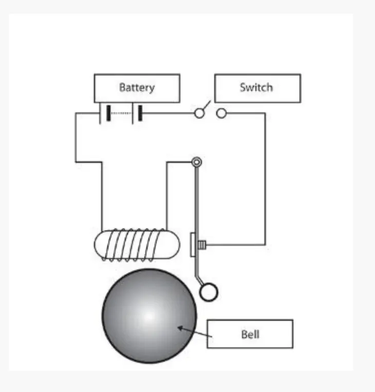
In the above arrangement, when the switch is closed the electromagnet receives electrical power from the battery and pulls the metal arm to hit the bell producing sound.
solenoid
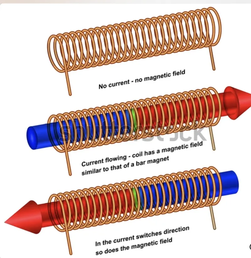
The solenoid is a coil of wire, and the plunger is made of soft iron. The magnetic field is formed around the coil when an electric current passes through it and draws the plunger in. We can say that the solenoid is responsible for converting electrical energy into mechanical work.
MODEL
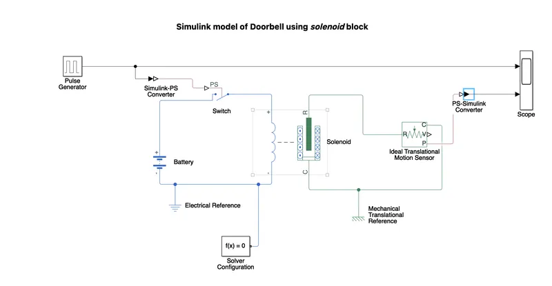
Picture of the block diagram of model is shown below
Steps
- Here we use a pulse generator to generate input signals
- Signal from pulse generator is converted to physical signal using 'SimulinK-PS Converter
- Solenoid is the main part of electrcical block
- Switch recieves the input signals
- One end of switch is connected to positive end of solenoid coil and the other end is connected to positive of battery
- An ideal transmissional motion sensor is connected to solenoid to take output from it
- Reference ports of both solenoid block and ideal translational motion sensor block is interconnected
- A PS-Simulink converter connects to the ideal translational motion sensor is converts the physical signal to simulink signal
- Scope is used to plot the input and outputs
- Electrical and mechanical references are connected to respective circuits
- Stop time is 20 secs
file of model is attached below (bell.slx)
Working
- Here we are giving electric current to coil from battery in a fixed interval by means of input signal from pulse generator
- The magnetic field is formed around the coil when an electric current passes through it and draws the plunger in and this movement of plinger results the movement of arm
Block parameters :pulse generator
Here we sets the period to 4 secs in order to sets time interval to 2 sec
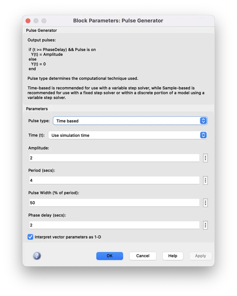
picture of the pulse created is shown below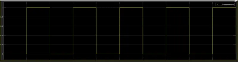
Output
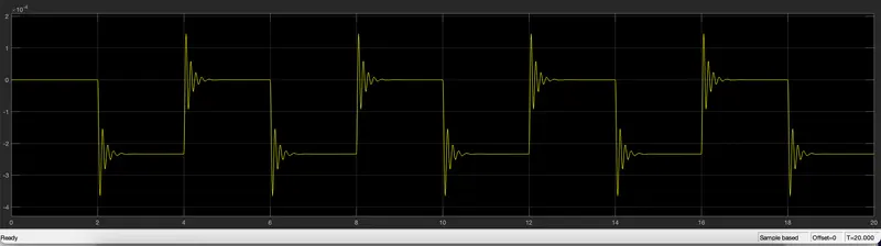
OBSERVATIONS
- From the plot we can see that plinger vibrates at a fixed interval
- It takes vibrations in two sets amplitude ranges
- Vibrations of the same amplitude range occurs alternatively
- Initially the amplitude of vibrations is high and then it decreases towards the end of each vibration
- This process repeats for the 'stop time' that we sets
CONCLUSION
- Created Simulink model of Doorbell using solenoid block where the switch is closed for 2 seconds and then released
- Observed the movement of plinger by the help of scope
- The results are satisfactory
TASK-2
AIM
. Use a thermistor to sense the temperature of a heater & turn on or turn off the fan as per the below conditions:
Temperature source: 20 °C from 0 to 10 seconds, 27 °C from 10 to 30 seconds, 23 °C from 30 to 50 seconds
Fan conditions: ON if the temperature above 25 °C, OFF otherwise
OBJECTIVE
Create a model using thermistor to turn off or on fan as per above mentioned conditions and simulate relation between temperature and resistance
THEORY
A thermistor is defined as a type of resistor whose electrical resistance varies with changes in temperature. Although all resistors’ resistance will fluctuate slightly with temperature, a thermistor is particularly sensitive to temperature changes.We here utilising this property of thermistor to sense the temperature change
MODEL
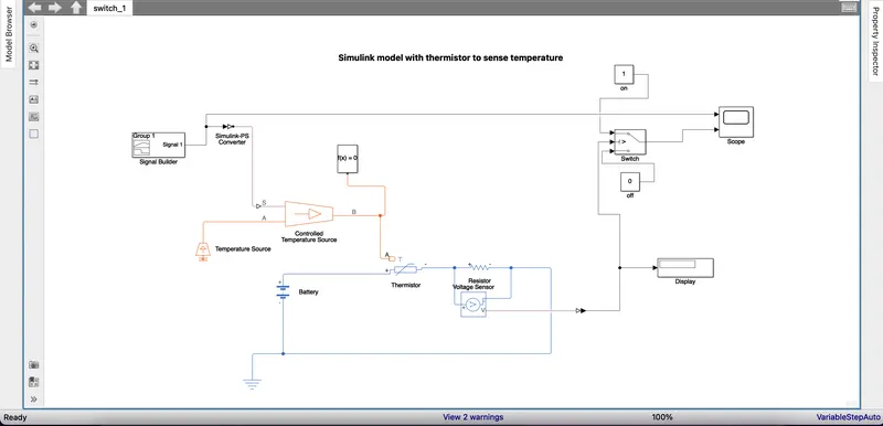
picture of the model is given below
STEPS
- We are making a signal by using signal builder.The signal made was according to input parameters mentioned in challenge
-
The signal made for temperature source: 293K(20 °C) from 0 to 10 seconds,300K( 27 °C) from 10 to 30 seconds,296K( 23 °C) from 30 to 50 seconds
- Then we converting the signal to physical signal by using simulink-PS converter
- Then we added a temperature source and controlled temperature source to diagram
- From the controlled temperature source we are giving the input to thermistor
- We are using a battery in electrical circuit
- Then we connects a resistance in series with thermistor and a voltage sensor in parallel with thermistor
- By this we can measure the voltage in that circuit
- We are giving signal according to temperature in electrical means to the thermistor,due to this resistance of thermistor changes
- V=IR, so any change in resistance should changes the value of voltage
- We are taking voltage as reference for the thermistor behavior
- For signals given to the thermistor we get corresponding voltages from the voltage sensor
- Voltage sensor is connected to display and a switch
- In the switch criteria for passing input is u2>threshold - fan gets on (system gives output as 1)
- Threshold is the voltage corresponding to the cut off temperature(298k)
- If u2<threshold output given by the system is 'constant o' fan gets off (system gives output as 0)
stop time is 50 secs
model is attached below(thermistor_1.slx)
Signal created in signal builder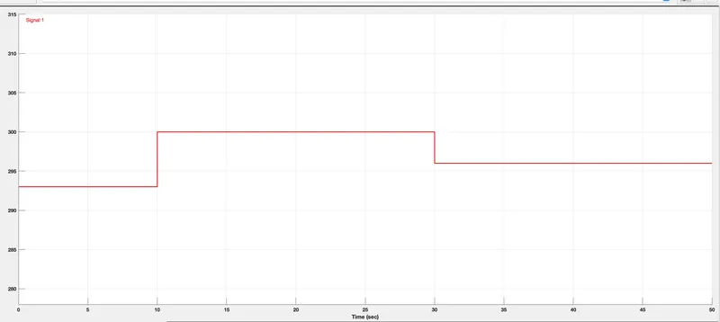
OUTPUT
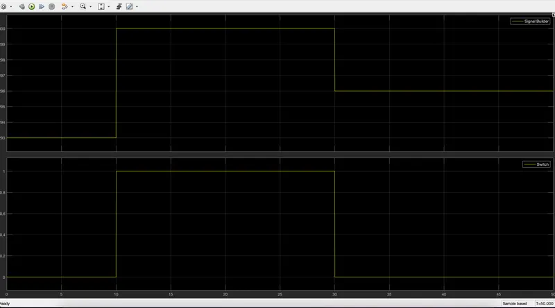
OBSERVATIONS
- From the plot we can see that for temperature above 298K(25 °C) the switch gives value 1 ,which means the fan gets on
- Also we can see that for temperature below 298K(25 °C) the switch gives value 0 , which means the fan gets off
CONCLUSION
- Model with thermistor is created to sense the temperature change
- Signal is created according to the temperature change
- Created a system which turns on and off according to temperature change
- By this simulation we can understand the relation between temprature and resistance