Week - 4
REPORT
Control logic of a Washing machine using Stateflow
Conditions
- If the power supply is available, the system gets activated
- If the Water supply is not available, stop the process & indicate through LED
- Soaking time should be 200s followed by Washing time of 100s.
- Then rinsing happens for next 20s & dryer runs for 50s
Simulink Model
StateFlow Model
Working
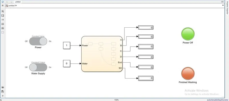
- The necessary blocks are taken from Simulink Library Browser.
- First Slider Switch is used for both power supply and water supply.
- Then Constant blocks are linked with these switches in order to regulate On and Off.
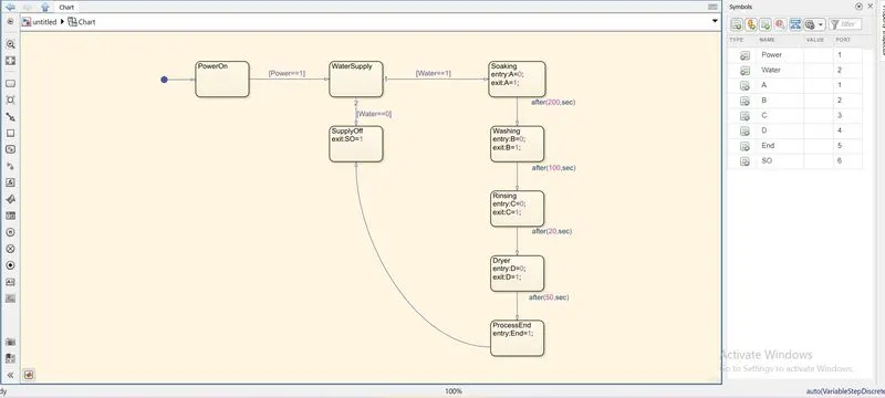
- Now Chart is used to define the StateFlow.
- In the chart window various blocks are used each denoting a particular function done by the machine.
- First the input signal is passed on to the PowerOn block then if value of Power is 1 then Watersupply is checked.
- If water supply is off then the system power off by passing signal to SupplyOff block.
- When water supply is on the signal passes to various process blocks like Soaking, Washing, Rinsing, Drying and the process is ended.
- The signal from the chart is connected to Displays. These connections are linked with Lamp block in such a way that when water supply is turned off then the system shuts down and Power off lamp indicates Green and Finshed washing lamp indicates Red. When water supply is on the process is carried out fully and turning the finished washing Lamp to Green.
- The 'Power Off' lamp is linked with the connection SO and Display while 'Finished washing' lamp is linked with the connection End and Display.
Simulink chart for the Gear shift logic
Conditions
Speed Range(kmph) Gear
0 to 15 1
16 to 25 2
26 to 40 3
41 to 60 4
Above 61 5
Simulink Model
StateFlow Chart
Working
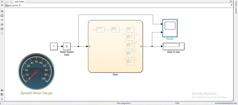
- A Slider Gain block is used for generating the speed variation. By using this block, variations in speed can be made during the simulation is running.
- A Cirlular Gauge from the library browser is used for indicating speed variations, using it as a Speedometer.
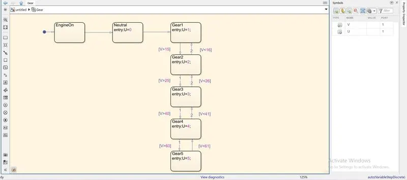
- Then a Chart block is used to process the gear shifting pattern as the speed varies.
- A Neutral Gear State block is used to indicate when the vehicle speed is 0 Km/h. Gear1 state block is used when speed changes between 1 and 15 Km/h.
- Gear2 between 16 and 25, Gear3 between 26 and 40, Gear4 between 41 and 60 and Gear5 for above 61 Km/h.
- The output U is marked as gear number displayed on the Display block and V is the input speed from the Slider Gain block.
- A Scope block is used to compare both speed change and gear change with respect to each other.
Result
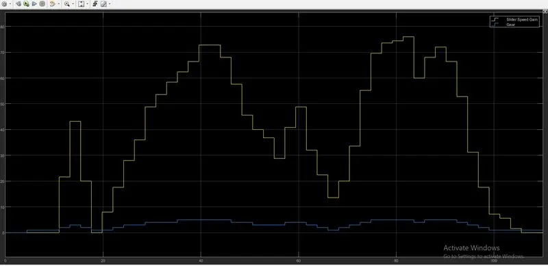
From the figure it is observed the random variations in the speed and gear changing accordingly. The yellow shows speed variations and blue shows gear number.
Google Drive link for Simulink Model
https://drive.google.com/drive/folders/1BHm6JFD37yvlkEkUZ5xHfQKcsOK9e5Fo?usp=sharing