Week - 4
objective:
Implement control logic of a “washing machine” using Stateflow as per given sequence:
If the power supply is available, the system gets activated
If the Water supply is not available, stop the process & indicate through LED
Soaking time should be 200s followed by Washing time of 100s.
Then rinsing happens for next 20s & dryer runs for 50s
After all the processes have completed turn on the finished LED
blocks used
chart:it is used to make the flow chart ,i have used this to make the washing machine logic.

constant:it is used to give input to the chart.

display:to display the output.
lamp: it is used to light when certain conditions are met.

explaination
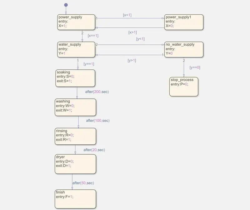
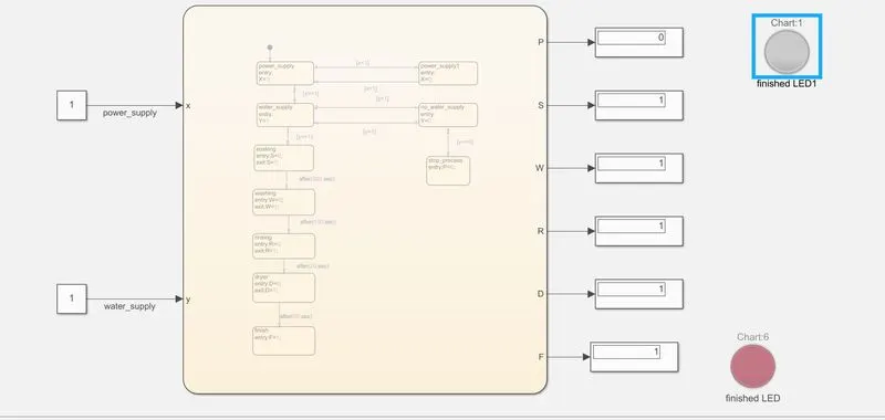
sequence is given in the question for the washing machine
now,we have to implement control logic
first i opened the chart and declared the state with default transistion and named it as power_supply
and made another state power_supply1 for OFF condition if (x<1) it is applicable and if (x>1) power_supply is ON
and move on to next transition.
next transition is applied if (x==1) and next state is water_supply and if water_supply is not available (y<1) the process will stop and LED will lit of RED colour.
if(y==1) it will move to next transition and next is soaking it will soak the clothes for
200 seconds(used delay after(200,sec)) and after 200 seconds it will move on to next transition
next transition is washing and it will wash the clothes for 100 sec(used delay after(100,sec) ) and after 100 seconds it will move on to next transition
next transition is rinsing and it will rinse the clothes for 20 sec(used delay after(20,sec) ) and after 20 seconds it will move on to next transition
next transition is dryer and it will dry the clothes for 50 sec(used delay after(50,sec) ) and after 50 seconds it will move on to next transition
next transition is Finish i.e the process is complete and LED will lit RED colour.
now ,we will use symbols pane to declare inputs and outputs.
now move outside the chart
connect the constant1 power_supply and contant2 water_supply as inputs
and connect the outputs to display
connect no_water_supply indicator to lamp and connect the finish to lamp to lit red.
now,i Run for 500 second.
2. Make a Simulink chart for the “Gear shift” logic as per below conditions:
Speed Range(kmph) Gear
0 to 15 1
16 to 25 2
26 to 40 3
41 to 60 4
Above 61 5
Give speed input while the simulation is running & display the gear number.
blocks used
chart:it is used to make the flow chart ,i have used this to make the washing machine logic.
constant:it is used to give input to the chart.
display:to display the output.
lamp: it is used to light when certain conditions are met.
circular gauage(as speedometer):it will diaplay the speed.

explaination
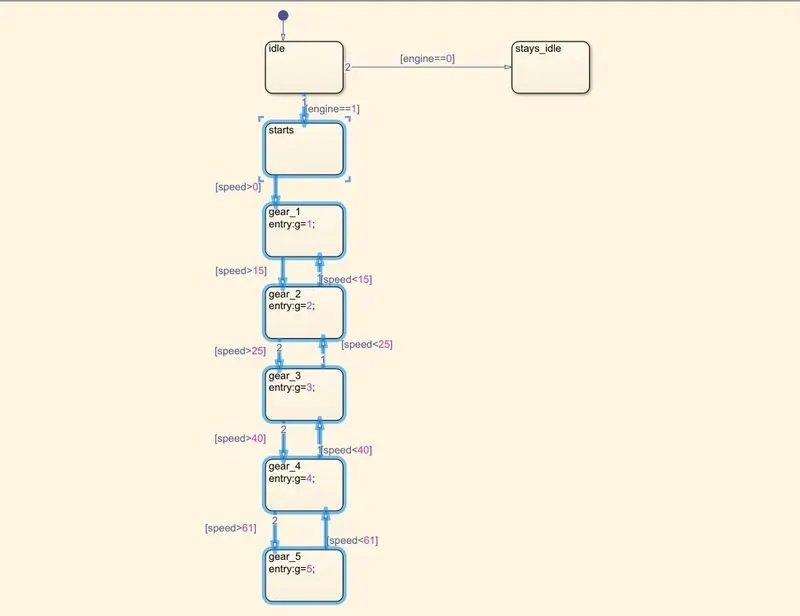
sequence is given in the question for the Gear shift
now,we have to implement control logic
first i opened the chart and declared the state with default transistion and named it as idle and if engine==0 it will stay idle and if engine==1 the engine will start
now,when speed accelerats above 0 it will move to next transition i.e. it will shift to gear_1 and when speed reaches above 15 it will move to next transition i.e. gear_2 and if it goes below 15 it will go back to gear_1
now,when speed reaches above 25 it will move to gear_3 and if it goes below 25 it will go back to gear_2
now,when speed reaches above 40 it will move to gear_4 and if it goes below 40 it will go back to gear_3
now,when speed reaches above 61 it will move to gear_5 and if it goes below 61 it will go back to gear_4
now ,we will use symbols pane to declare inputs and outputs.
now move outside the chart
connect the constant speed and constant1 engine as input
connect speedmeter to input speed and it will display the speed.
and connect the outputs to display
connect gear display to five lamps and
if value is 1 gear_1 is lit green
if value is 2 gear_2 is lit green
if value is 3 gear_3 is lit green
if value is 4 gear_4 is lit green
if value is 5 gear_5 is lit green
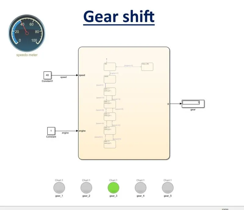
when speed is above 26 and below 41 the gear will shift to gear_3 and gear__3 is lit green
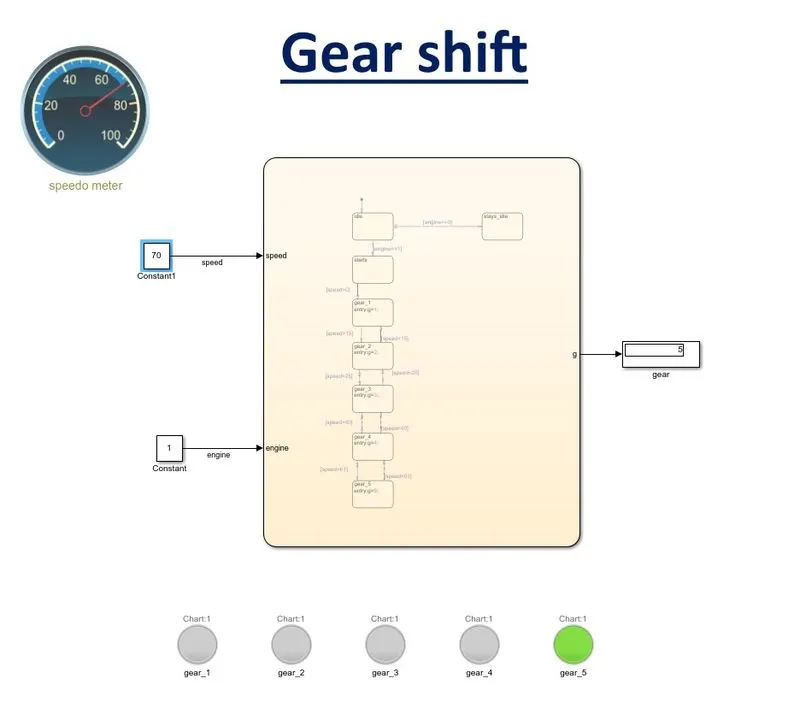
when speed is above 61 and below 61 the gear will shift to gear_5 and gear__5 is lit green
conclusion
1. control logic of a “washing machine” using Stateflow is working properply.
2. gear___shift is working properply.