Week - 4
- Implement control logic of a “washing machine” using Stateflow as per given sequence:
- If the power supply is available, the system gets activated
- If the Water supply is not available, stop the process & indicate through LED
- Soaking time should be 200s followed by Washing time of 100s.
- Then rinsing happens for next 20s & dryer runs for 50s
Modeling of washing machine in simulink:
These are the following things we need for modeling the subsystem washing machine logical block diagram setting:
- slider switch
- constant
- stateflow
- display
- lamps
control logic of washing machine using stateflow:
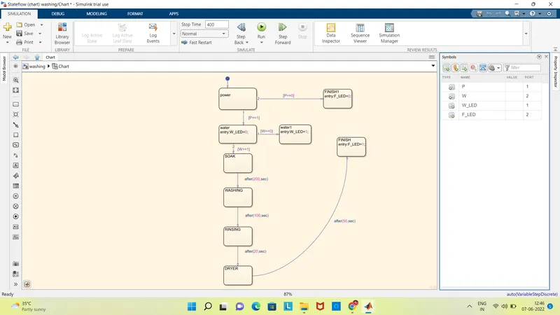
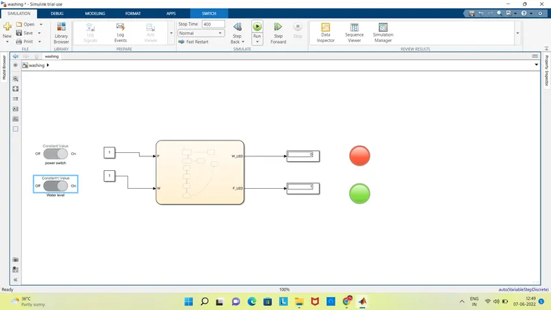
Simulink model of the system when power and water supply is available.
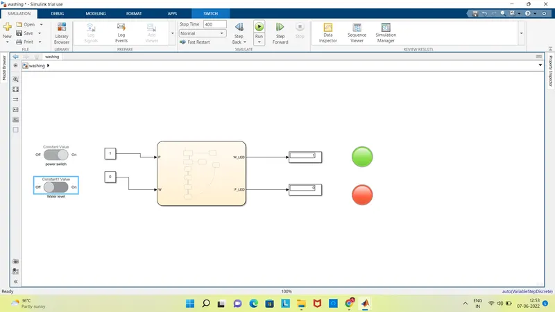
Simulink model of the system when power is ON and water level is OFF:
The process of the washing machine is the input of power supply and the water level .The outputs are soaking, washing, rinsing, dryer it depends upon some time period to finish the work.
The indicator show the ON and OFF indication through LED light.
2. Make a Simulink chart for the “Gear shift” logic as per below conditions:
Speed Range(kmph) Gear
0 to 15 1
16 to 25 2
26 to 40 3
41 to 60 4
Above 61 5
Give speed input while the simulation is running & display the gear number.
In the gear is the process of continuous action. A gear shift mechanism for a manual transmission includes a shaft axial movable for selecting shift planes and rotatable for engaging the gears defining the shift planes. the shaft is held in a reference shift plane by two helical springs.
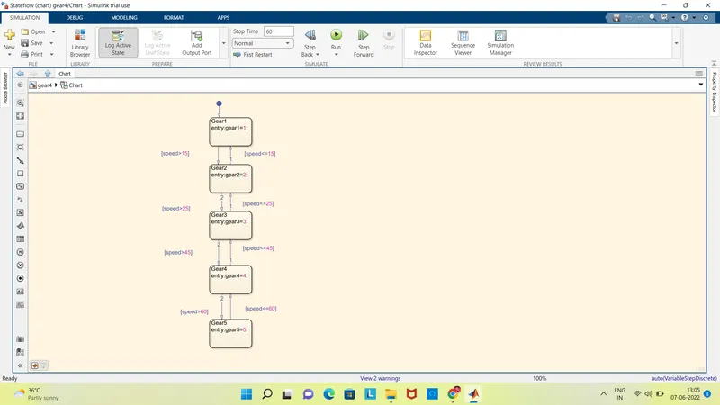
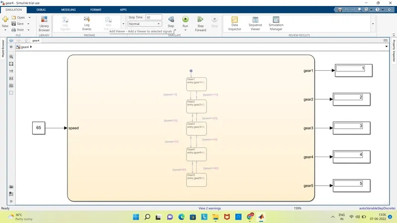
finally we get the result as, when the speed in above the 61 kmph then it is 5th gear. To slow down the speed we have to reduce gear.