Week - 4
Title :
- Implement controllogic for washing machine in state flow.
- Make a simulink chart for a gear shifter at a varying speed.
A.
WASHING MACHINE
Explanation :
- Washing machine is a device which is used for the laundry cleaning, soaking, washing and drying up which can be seen in almost every home nowdays.
- The adds used for the cleaning of the dirty laundry is water and detergent.
- The following setup shows the washing machine flowchart for the particular time as given.
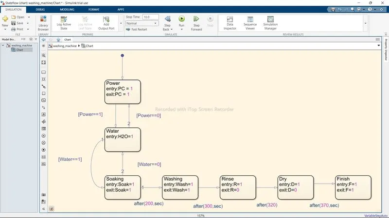
- In the above chart the first block is of the input power supply which gives up the power support. The power pass through thats why the entry and exit point is 1.
- further the water is input as shown the connections are made showing the arrows as the power flows only unidirectional.
- Further the flow is connected to the Soaking block. this isthe block where the washing of the clothes begins.
- Water inputs are given so that the water does not revert back to the original.
- From soaking it moves to waashing. In wasing the twist and turning of the machine bucket can be seen, taking the dirt ou clothes.
- The time between soak and wash is 200 sec. which means the soakoing process will continue for 200.sec.
- After wasing the clothes are rinsed which has entry as 1. The washing to soak is given as 100 sec which is added into the time consumed by soaking i,e. 200sec. Which gives us the time of 300sec.
- After rinse The laundry is dried off by spinning the machine bucket at the high speed. which allows the clothes to throw out the water while washing because of centrifugal force.
- The Drying process is started 20 sec after the rinse which gives that 20 sec must be added to the rinsing.
- At the last the Machine is stopped and the finish lamp blinks up indicating that the laundry is ready to take out from machine.
- The below picture shows the actual simulink state flow of washing machine.
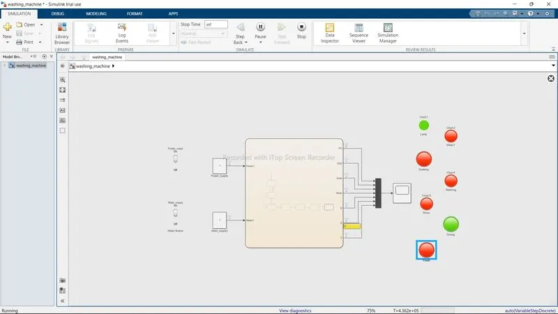
- In the above figure as shown the stateflow chart is connected to the constant inputs which are the power suppy and the water supply to the stateflow.
- These Constants are connected to the switchkey. Key turns on and off while running the simulation for inf number of times.
- The stateflow is forward as the multiple outputs as the main lamp indicationg power, the water output,soking,washing,rinsing,drying and finishing off the process.
- All these outputs are connectd to their respective lamps which blinks when the supplyis on or running or act accordingly to the input like power and water as shown.
- These output are connected to the mux which merge all the outputs and forwarding the single output signal to the scope.
- The graph of washing machine shown by the scope is given below.
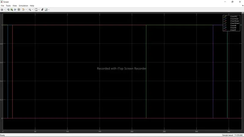
The above graph shows the representation of the process going through the circuit.
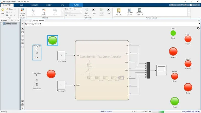
- When the switch of power or water supply is turned on and off the machine and their output lamp function accordingly.
- When the water supply switch is turned off the lamp connected to the constant water input turns red and affect the output, same as with input as well.
- what happens when the input switches turn and off while simulation is shown in the fig below.
B. GEAR SHIFTER SIMULATION
Explanation :
- In the vehicle weather CI or SI engine the gear plays and imp role.
- gears allows the vehicle to achive high speed at low torque or vice versa for hill climbing.
- in this setup of state flow chart engine gear simulation is given usong the given inputs. the stateflow chart for the gear shofter is given below.
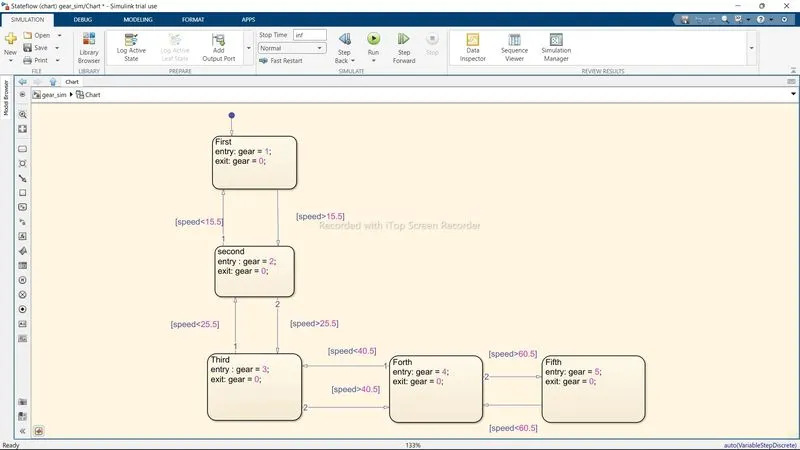
- In the above chart it is seen that the arrengements of blocks are done according to the flow.
- First block gives the first gear entry which defines that the first block will only work for the gear level 1.
- The second block gives the input of second gear which defines that the second block comes after the first, as it is manual and sequential gear shifter.
- The first and secind block have connections which shows that if the speed of vehicle goes beyond 15.5 then the vehicle is shifter to second gear or else it stays on one.
- Similarly the thrid gear connections are made and the entry is given to be 3. In the third gear block the speed of second gear is set to be 25.5. It means the limit for the second gear is set to be 25.5.
- In fothe block gear no 4 is assigned and the connections made between third and forth gear is given to be speed limit as below 40.5 for third gear, which indicates that the speed above 40.5 will be assigned as forth gear.
- Last block is of the fifth gear which is assigned as the entry as 5 which is mad ethe connection with the forth block as the speed above 60.5 is set to be in fifth gear.
- The below fig shows the setup for the gear simulation.
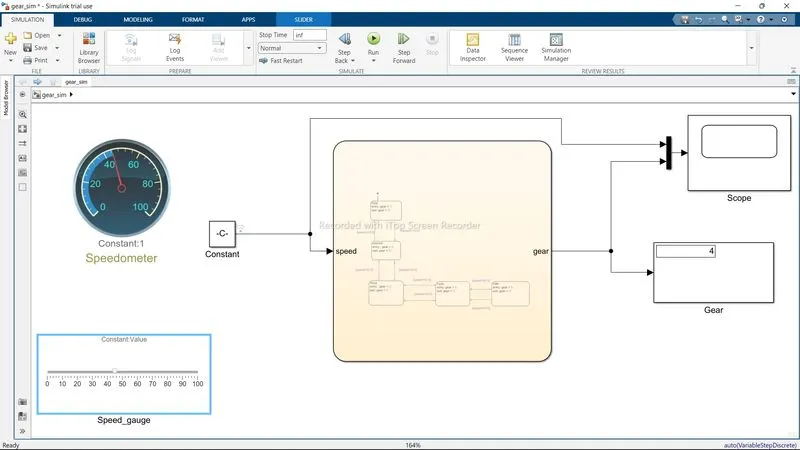
- As seen in the above picture the setup comprises of the circular gauge, slider, scope and display.
- The constant block is given as an input to the state flow chart.
- The circular gauge and slider both are connected to the constant block.
- The output of the stateflow is connected to the display and scope blocks. The display block will gives us the gear number whie performing the simulation and scope block will give the graph of it.
- After making up all the connections to the respective gauges the simulation is run for the infinite no of seconds.
- wile running the simulaton the slide is used to increse and decrease the speed which will show the speed on the gauge which is a soeedometer and the number of gear for that certain amount of speed is given is the display block.
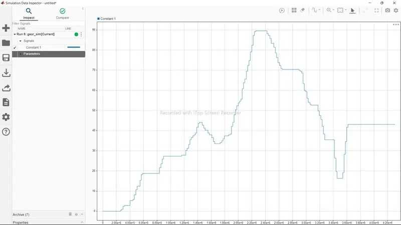
- The log signal is made a connections with the input which gives the graph about the varying or fluctuation to the speed done while performing the simulatuion as below.
Hence both the simulations are performed successfully.