Week - 4
Question 1: To implement the Control Logic of a Washing Machine using Stateflow in the following sequence:
- If the power supply is available the system gets activated.
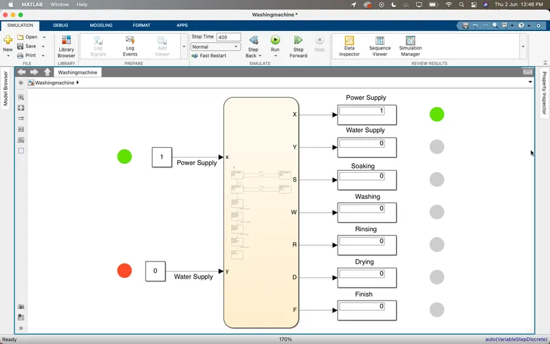
- If the water supply is not available, stop the process and indicate through LED
- The soaking time should be 200 secs followed by a washing time of 100 secs.
- Then rinsing happens for the next 20 secs and Drying for the next 50 secs
After all the processes have been completed turn on the Finished LED.
Procedure:
Working Principle of a Washing Machine
A washing machine spinning at 1000rpm helps soap and dirt with it to leave the surface of the cloth via centrifugal force and into an outlet pipe hence utilizing centrifugation to both clean and partially dry the clothes loaded in it. Thus the processes are electrically controlled, such as the drum, valves, pump, motor and heating. The valve opens again and the dirty water drains out. The pump works to help get rid of water. The valve lets clean water in again into the drums. The four process are:
- Soaking
- Washing
- Rinsing
- Dryer
Control Logic of a Washing Machine:
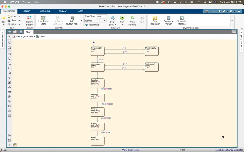
It checks for the extent of dirt and grease, the amount of soap and water to add, the direction of spin and so on. The machine rebalances the washing load to ensure correct spinning. Else, it reduces spinning speed if an imbalance is detected. Even distribution of washing load reduces spinning noise.
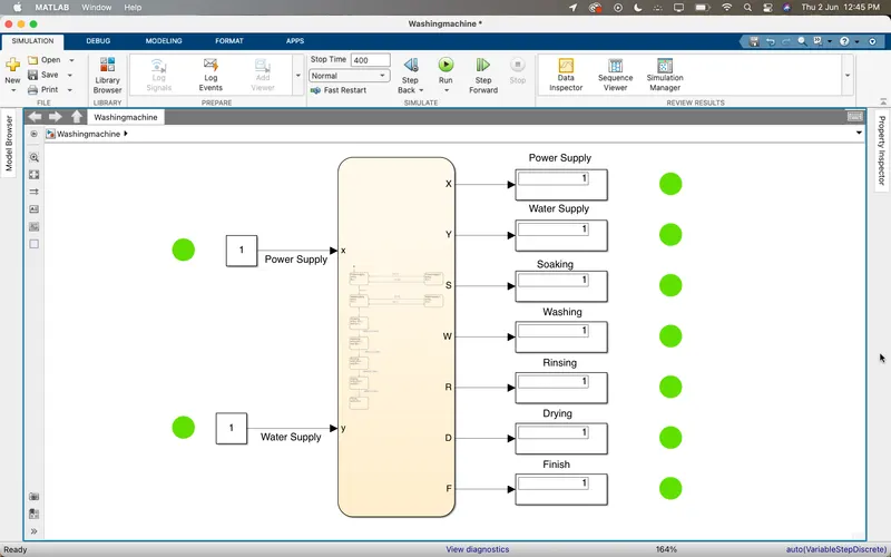
The two inputs are given for the power and water supply. Once the inputs are given outputs are displayed by the flow chart as per the given sequence. The system are observed for sometime then it is checked and the process is completed by green light as displayed.
Question 2: Gear Shift Logic
Make a simulink chart for the Gear Shift logic as per below conditions:
| Speed Range(kmph) | Gear |
| 0 to 15 | 1 |
| 16 to 25 | 2 |
| 26 to 40 | 3 |
| 41 to 60 | 4 |
| Above 61 | 5 |
Stateflow
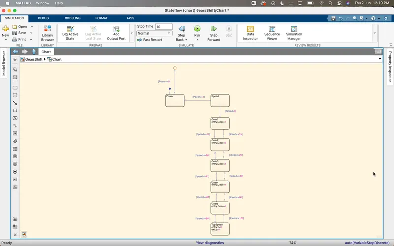
Explanation:
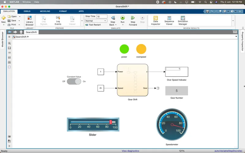
1. To create a Simulink model of gear shift create a Stateflow chart and start with the power block which is connected to the breakpoint and a junction with power==0 condition and connected to speed block power==1 so that when the speed is above 1 the process will start flowing to gears.
2. Here I have mentioned speed to Conway our conditions as above speed greater than zero the gear shift should start the cycle of changing to next gear.
3. In gear one, the breaking point is mentioned up to 16 kmph it is respectively changing to 61 kmph.
4. From gear 5 to gear 1, the speed is decreased till zero so that we can shift our gear not only increasing it can be decreased too.
5. Topspeed is a state where the speed has been increased above 80kmph, there is a light which indicates over speed in our Simulink block.
6. After completion of the chart, we can see the inputs power and speed, outputs gear and to speed (z).
Results:
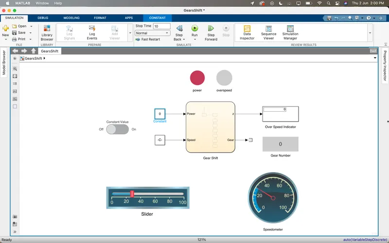
Power OFF
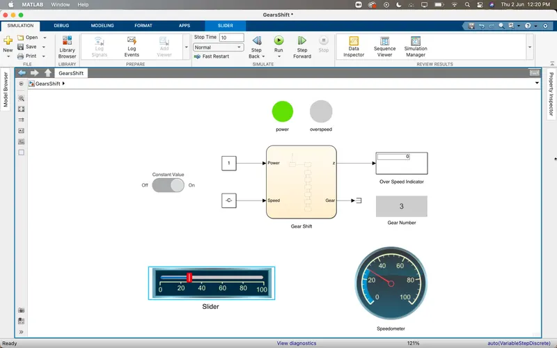
Power ON Speed above 20kmph
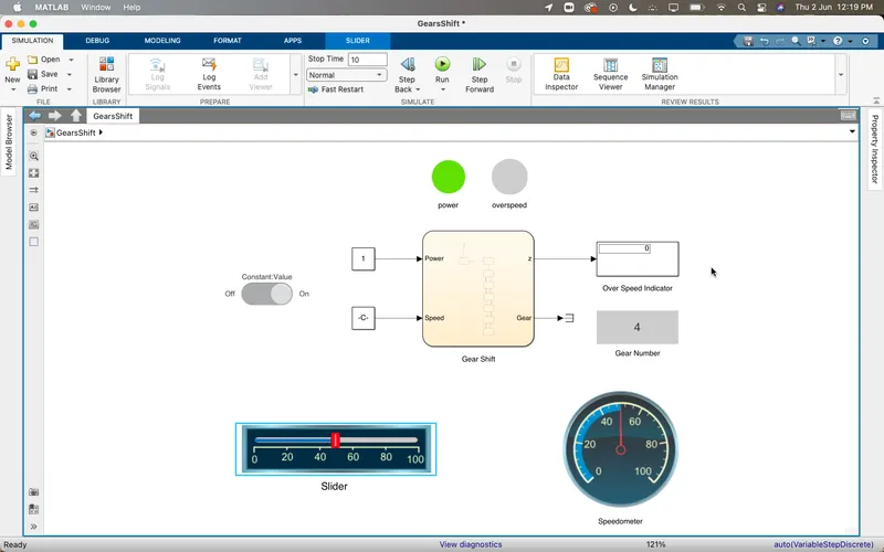
Power On speed above 40 kmph
Overspeeding above 80kmph