Week -2
Aim: To make a Simulink model of a doorbell using a solenoid block.
Simulink Model:
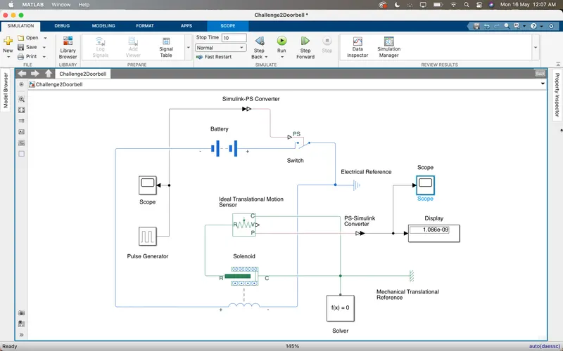
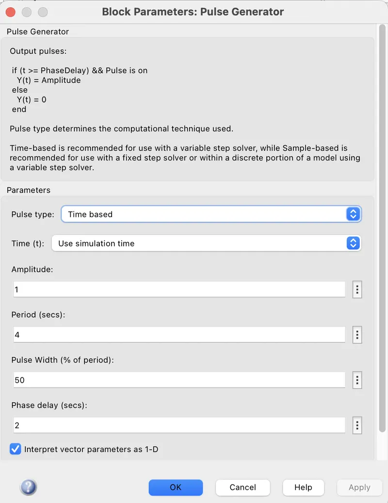
- The pulse generator is used to create square wave pulses at regular intervals. The block waveform parameters Amplitude, pulse width, period and phase delay, determine the shape of the output waveform.
- The switch block used is controlled by an external physical signal. If the external signal is greater than the threshold parameter then the switch is closed, otherwise, the switch is open.
- The solenoid block is connected to the switch and battery and we will get a complete electrical circuit. Part C is connected to the mechanical reference.
- The ideal translational sensor is connected with solenoid block R to observe the movement of the plunger.
- Scope is connected with the ideal translational sensor to get the output.
- PS-Simulink converter is used to convert the physical signal to simulink signal.
- Solver Configuration: Each physical network represented by a connected simscape blocked requires solver setting information for simulation.
- Electrical and Mechanical References is a reference block with which the system has a ground source as a base.
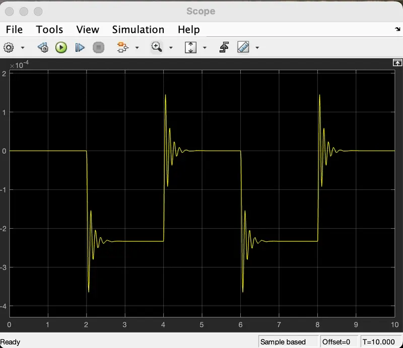
Input Signal
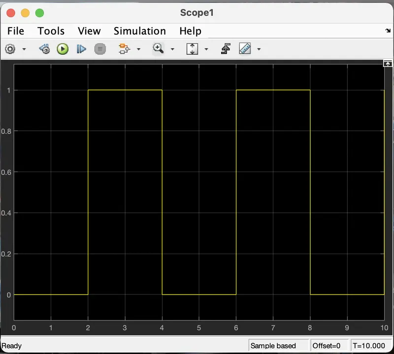
Output signal
2. Use a thermistor to sense the temperature of a heater and turn On and Off the fan as per the below conditions:
Thermistor: Thermal Resistor is defined as a type of resistor whose electrical resistance varies with changes in temperature. Although all resistors' resistance will fluctuate slightly with temperature, a thermistor is particularly sensitive to temperature changes.
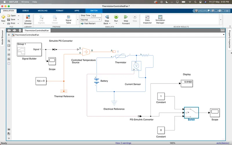
The Thermistor acts as a passive component in a circuit. They are an accurate, cheap and robust way to measure temperature. While thermistors do not work well in extremely hot or cold temperatures, they are the sensor of choice for many different applications. Following is the Simulink block assembly for Thermistor based heater.
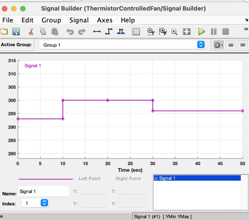
Input:
1. 0-10 secs temp 293K
2. 10-30 secs temp 300K
3. 30-50 secs temp 296K
In this model the following blocks are used:
1. Thermistor: Temperature sensing element, Negative temperature coefficient thermistor using B-parameter equate.
2. Controlled temperature: The block represents an ideal energy source in a thermal network that can maintain a controlled temperature difference regardless of the heat flow rate.
3. Signal Builder: Function to create and access the signal.
4. DC voltage source: The DC Voltage source block maintains a time-invariant (constant) voltage across its output terminals, independent of the current through the source.
5. Voltage Sensor: The block represents an ideal voltage sensor, that is a device that converts voltage measured between any electrical connections into a physical signal proportional to the voltage.
6. Switch: The switch block passes through the first input or the third input signal based on the value of the second input. The first and third inputs are data input. The second input is a control input. Specify the condition under which the block passes the first input by using the criteria for passing first input and Threshold parameters.
7. Electric and Mechanical references.
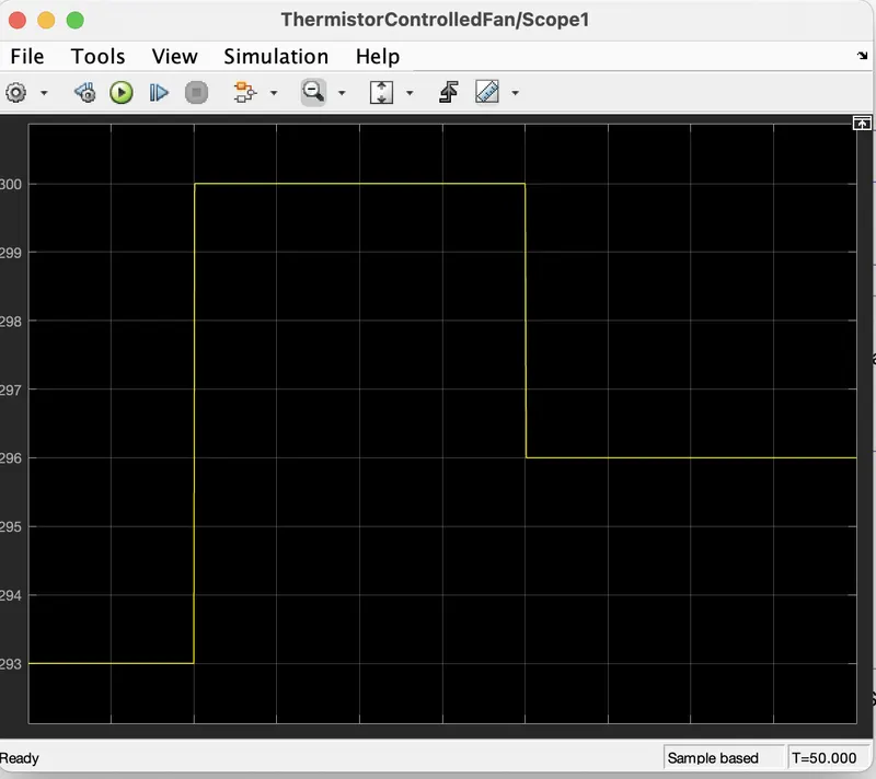
Output:
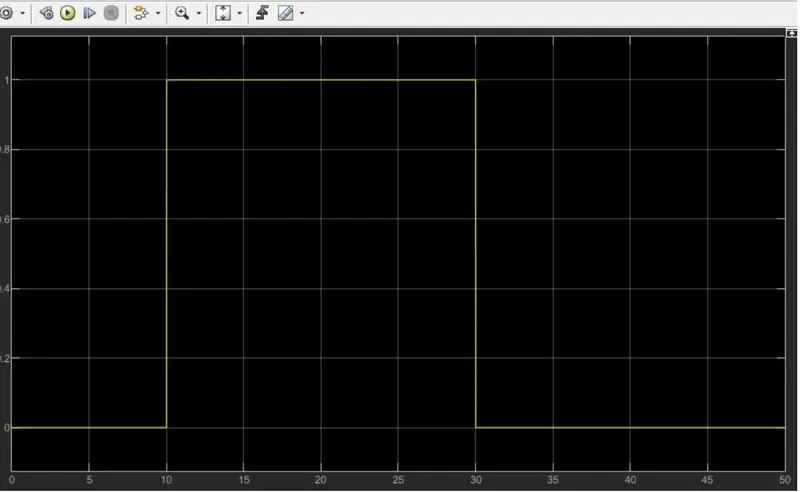
Switch is On between 10-30 secs when the temperature is above 25 degrees.