Week - 4
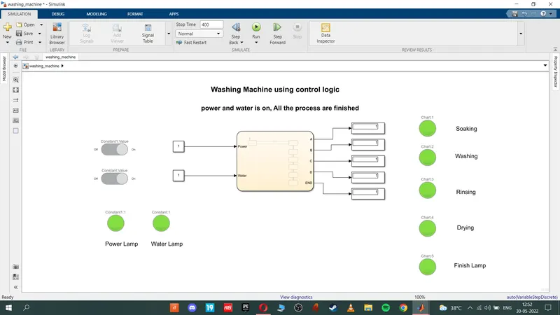
1. To Implement control logic of a “washing machine” using Stateflow as per given sequence:
If the power supply is available, the system gets activated
If the Water supply is not available, stop the process & indicate through LED
Soaking time should be 200s followed by Washing time of 100s.
Then rinsing happens for next 20s & dryer runs for 50s
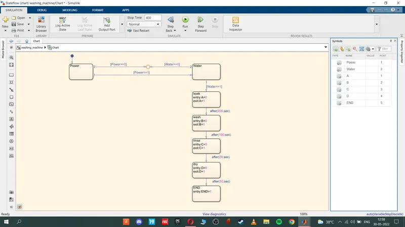
State Flow:
Stateflow provides a graphical language that includes state transition diagrams, flow charts, state transition tables, and truth tables. You can use Stateflow to describe how MATLAB algorithms and Simulink models react to input signals, events, and time-based conditions.
Inputs in the state flow:
1. soaking = 200 sec
2. washing = 100 sec
3. Rinsing = 20 sec
4. drying = 50 sec
this inputs are used in the state flow by control logic
Control logic and explanation:
1. we need a power and water to run the washing machine.
2. power and water are our input.
3. if the power is flowing through the system the process starts
4. if the power and water is flowing in the system the process full started and finished
5. if there is no power the process wont start
6. the various parameters are implemented in the stateflow.
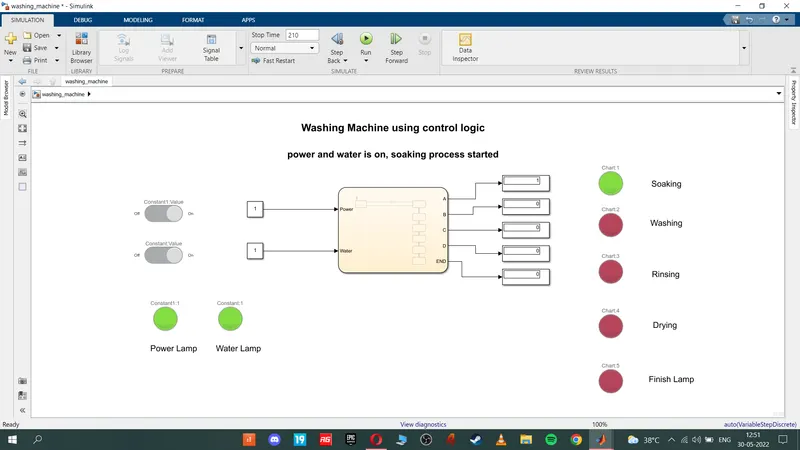
7. Around 200 sec the soaking process starts.
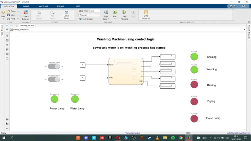
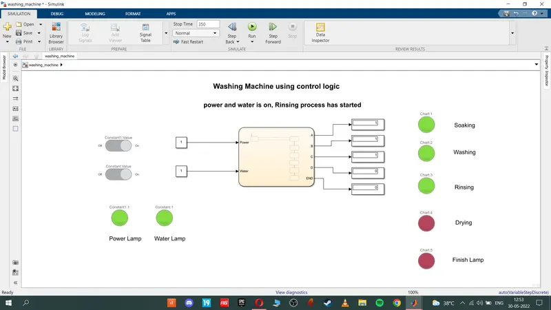
8. after that all the process start in their determined time
9. process comes to an end
7. using the lamp to justify which process is running in the defined time.
8. using control switch to turn on and off the water and power (inputs)
Blocks used:
Constant block for the input defining purpose
slider switch to turn power and water on and off
lamp for the indication purpose
display to show output
Model:
State flow:
Soaking process:
Washing process
Rinsing process:
drying process and all process came to an end and process stops
2. To Make a Simulink chart for the “Gear shift” logic as per below conditions:
Inputs: Speed Range(kmph) Gear
0 to 15 1
16 to 25 2
26 to 40 3
41 to 60 4
Above 61 5
blocks used:
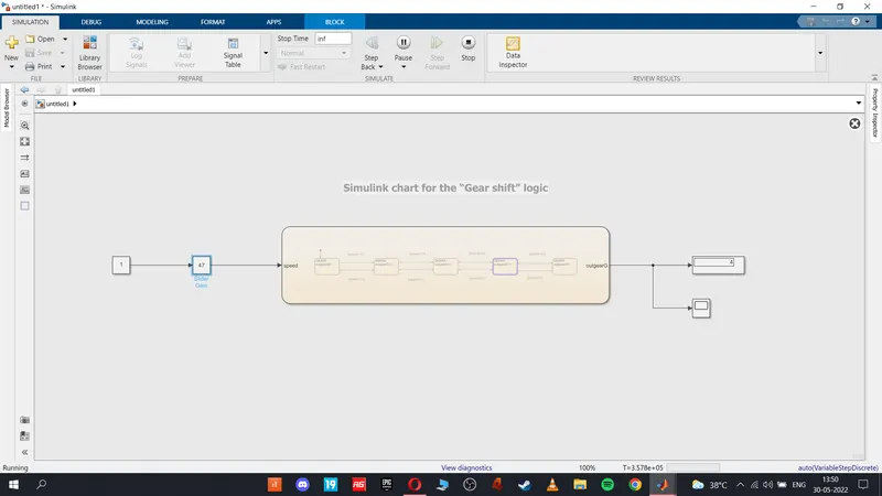
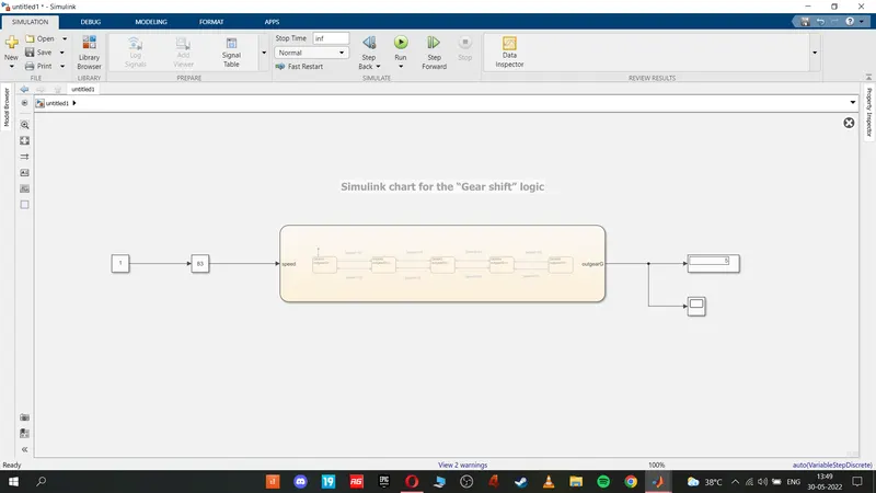
1. constant block to multiply with slider gain block
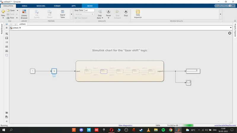
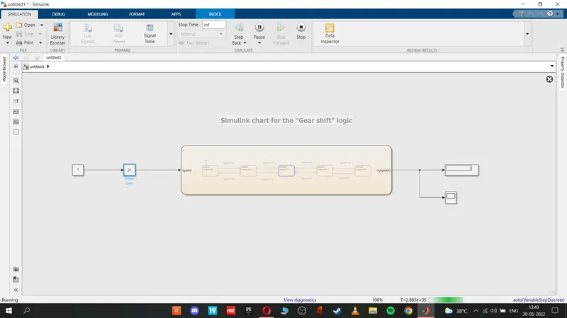
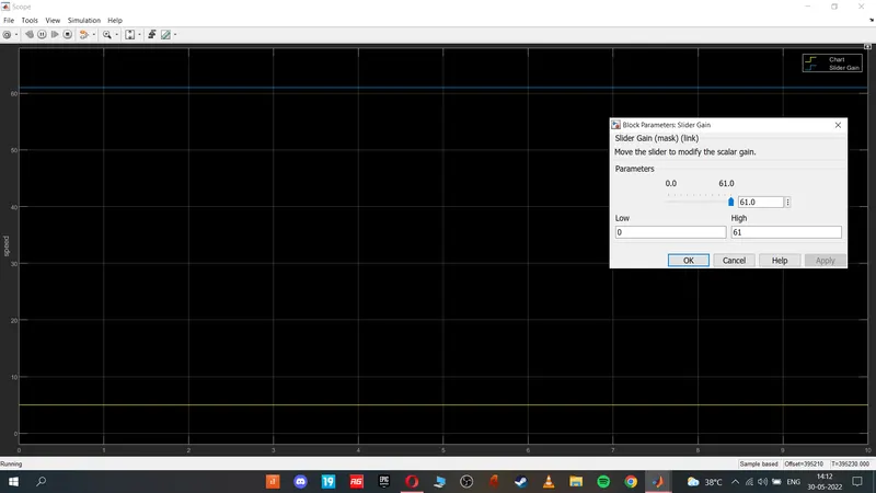
2. slider gain block is used to accelerator in this case when we increase the speed we can observe the shifting of gears
3. in stateflow we gave the inputs and we got desired output
4.display- to observe the gear shift
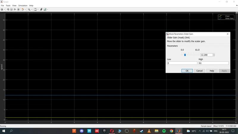
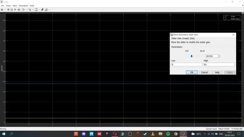
5.scope to examine in which speed the gear shift occurs
Explanation:
1. when we input a number in the slider gain, in state flow it checks the input and display the gear number according to our input
Speed Range(kmph) Gear
1. 0 to 15 1
2. 16 to 25 2
3. 26 to 40 3
4. 41 to 60 4
5. Above 61 5
Model:
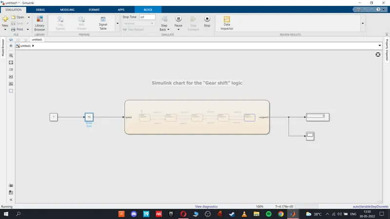
stateflow:
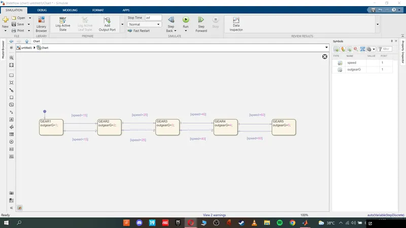
gear 1:
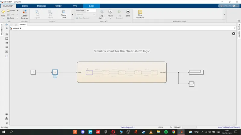
gear 2:
gear 3:
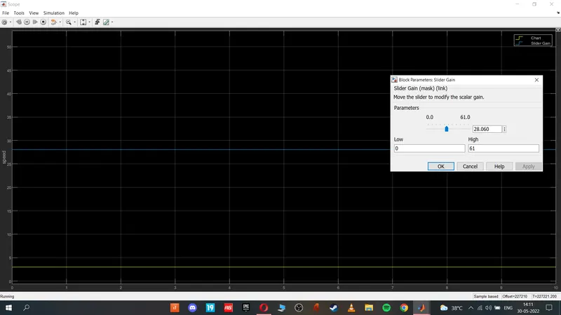
gear 4:
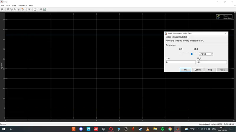
gear 5:
conclusion:
1 . from the model we see that we Implement control logic of a “washing machine” using Stateflow and all the process are completed
2. from output we see that gear shift logic has been inplementes using stateflow