Week - 4
1) To implement the control logic of a washing machine per he given conditions given in the question using state flow.
CONTROL LOGIC : By control logic of a washing machine we mean that how the controls of a washing machine are done depending upon the logic. basically the control logic of a washing machine depends upin time delays and the input conditions.
STATE FLOW: State flow is a process in simulink which is used to implement the control logic and is similar to flow chart used in c++ or script. In simulink state flow is implemented by using chart block from simulink library. In the chart block we can create the control logic of any system by giving inputs, conditions and feedbacks depending upon our logic.
CONTROL LOGIC FOR OUR CONDITION : in our our question it is mentioned that the system gets only activated when the following conditions are satisfied and when they got activated the system undergo the other operation depending upon the time delays given.
(1) input condition: It is mentioned the system get activated only when the input power is turned on. Here the switching operation on and off is compared with high and low of binary language. ie when s specific opertion is going on i have considered that operation to be high ( equals=1) and if the operation is not on then it is considered as low(equals =0)
Images of state flow is pasted below

steps for creating state flow in simulink
(1) double click in the simulink model window and type chart
(2) we get the chart block on double clicking the chart block the chart block will get open
(3) in the chart book there are different tool boxes are available from that state is sletected
(4) then the state will appears as a square box and in that we can mention the output
(5) depending upon the states requirements we select the state the first state will come with a default entry
(6) we can connecting states by click and drag from the respective borders
(7)then the transition arrows will appear between state and in that arrow we can mention the input , output condition
(8) after crosschecking the input conditions the respective states got initiated
(9)the variable given inside the state can be mentioned as output or the condition given to the transition line can be mentioned as input from symbols pane option avaialbe in configuration and simulation
states
1) first state: switch (since it is feeded by entry it will always show value high i.e 0n= '1' alwa) and the state will always get executed and the led correnponding to' on' will be always green
2)second state(state name water):sine the first state always get executed the condition of power==1 and power==0 is examined if power==0 then the state will be switched to state name stop and this state got initiated and stop shows value=1 and stop corresponding led will blow in green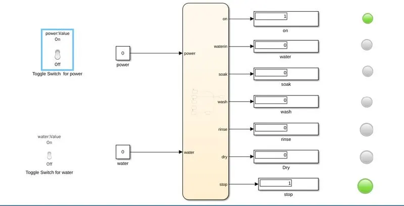
when the value of power==1 the state 2(water get initiated and ) waterin will show value high and will blow in green the image is pasted below
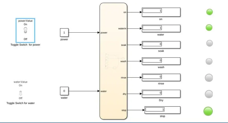
state3: after state 2 the chart is made to examine the condition water==1 and water==0.when water==0 the system switches to stop. and we wil get the same image as i mentioned just above and the state soak will not get initiated. and the stop ledwill blow in green
and when water==1 the system switches to soak the image is pasted below and in this condiion i have taken stop time equals=200sec
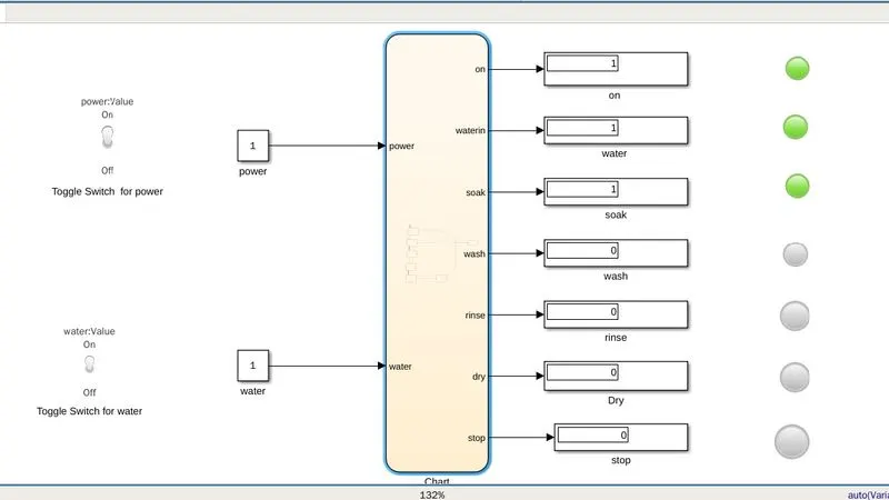
state4: if we had increased the stop time from 200 to 300 sec then after(200,sec) condition is satisfied and the system completes soaking and switches to washing if power==1 and water==1. The image is pasted below
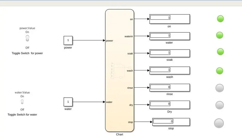
state5:if we had increased the stop time from 300 to 320sec then the condtion after(100,sec ) is satisfied. after washing for 100 sec the system switches from state 4 to state 5 and now we can see that on,waterin,soak,wash andthe rinse led has blown in green since the conditions are satisfied. the image is pasted below
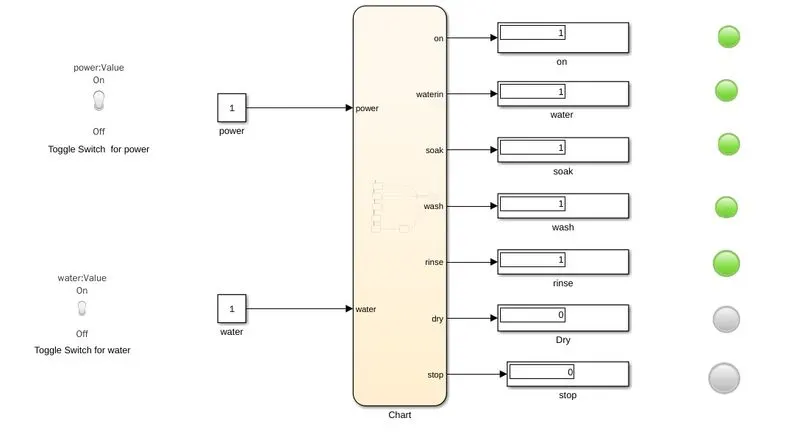
state6:if we had increased the stp tme from 32o sec to 400 sec we can see that after(50, sec) condition is also satisfied and the system completes the chart which was created and all the led willbe blown green. The imae corresponding to stop time 400 sec is pasted below
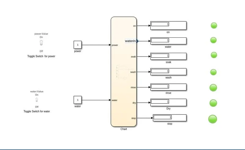
simulink model of washing machine
blocks:
(1) chart block: as i have created the chart block with two inputs and 7 outputs the chart block is appeared
(2) constantblock: i had used two constant block with value as "1' to provide the value of power and water equals one
(3)toggle switch: in order to perform switching operation i had selected two toggle switch from the dash board library and connected to the input blocks power and water by the connect option available on the upside of the block and then undergodone connecting of the toggle witch block
(4) display: The respective outputs are connected to display block to see the value whether the are showing a high or low
(5)lamp: this is also a dash board library block and is connected to the respective display blocks using the connect option available when clicking the block. on double clicking the lamp block we can cofigure the colours of lamp
Input
input high and low are given by toggle switch connected to the constant blocks. I had given the stop time as 400 sec. depending upon the inputs and stop time the state flow get executed
output
we can see the respective outputs through the led indication and the display. By double clicking the chart optin and by using step option near the run in simulink we see the state flows within the chart
2)
chart for gear shift logic
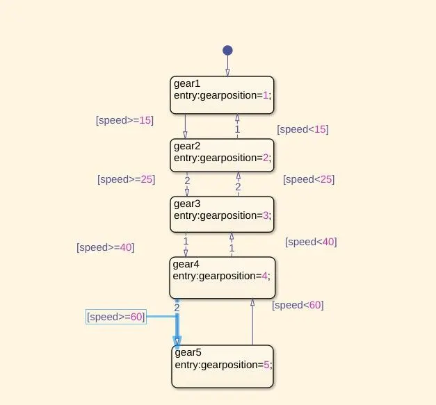
The image above shows the chart of gear flow with input mentioned as speed and gear position mentioned as output by the option symbols pane available in configuration and simulation
How the chart is made
step1:
from the simulink blank model page on doing double click and type we get the chart block. on opening the chart block by double clicking the chart block got openned an we can see different tools on the left of the window
step2;
fromt the to window i have taken five states in the states the state name has given gear1, gear2, gear3, gear4,and gear 5. The first state will appear with a default entry
step3:
in each state i had mentioned gear position and the states and connected through transition arrows on the transition arrows i hand mentioned speed condition. In the symbols pane i have mentioned gearpostion as output and speed as input
operation
as the transition line between states are given speed limit condition and the speed crosses these condtion the system switches states and the postion will be indicated in gear position since it is mentioned as output. since each state are provided with feedback transition line and they are also given with condition when the speed decreses the gear shift backs ie when the speed becomes greater than or equal to 15 the system switches and gear postion indiacte gear '2" and if speed decreases below 15 gear position switches state and shows value "1". similarlly if the speed crosses 25 oe equal to 25 the gear position indicate gear position"3'',speed increases greater than or equals to 45 the gear postion shows "4" and if decreases below 45 it goes to gear "3" in this way the represented gear logic works between gear 1 to 5
simulink model
since in chart we have one one input and one output we get a block similar to the below shown image
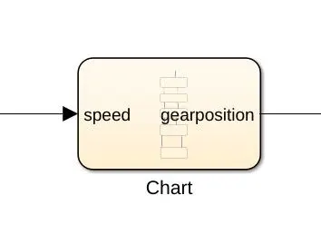
block used in the output
display: to view the gear postion depending upon the speed
scope: to view and examine the output
block used in the input
slider gain block: since i have to vary the speed i had used a slider gain block
advantages of slider gain block: in slider gain block we can change the value of input during simulation. but the important thing to be noted while using the slider gain block s that if we use the slider gain block without any input it willnot show any syntax error
constant block: in order to satisfy my variying speed condition during simulation i had feeded the slider gaiin block with a constant block
guage : the guage block is selected from the dashboard library connected by using connect command and will show an analog image of the input given through slider gain
inputs and outputs
speed<15
when we had given a speedequals 12 through slider gain we get the blow image
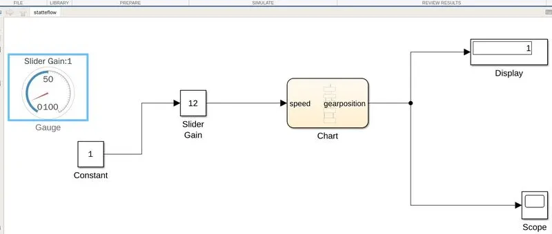
0utput: the display shows gear postion '1'
speed>==15
given speed equals 22 through slider gain
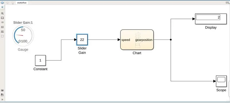
output: in the display we can see the gear position as'2' condition satisfied
speed>=26
if we give speed equals 26 or greater than 26 then the system switches to gear'3'. i had given speed equals 26 in this condition
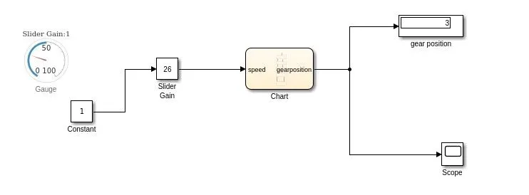
output: In the display we can see gear position equals '3'
speed>=40
if we give a speed equals or greater than 40 the gear will be shifted to'4'. i had given speed equals42 through slider gain
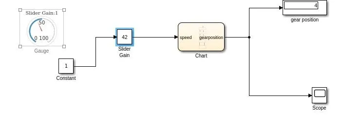
output: in the display we can see gear position '4' for speed 42
speed>=61
if we give a speed equals to or greater than 61 then the state will be shifted switched to gear '5'. here i has given speed equals '64' through slider gain
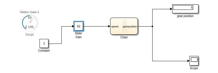
output: in the display we can see gear postion"5" for speed equals 62
NOTE; SINCE EACH STATES ARE PROVIDE WITH FEEDBACK TRANSITION CONDITIONS WHEN SPEED FALLS BELOW ,THE SYSTEM SHIFTS BACK TO THE PREVIOUS GEAR