Project
PROJECT
AIM
To carryout a system simulation of an all terrain vechicle. specially BAJA All terrain vechicle which uses CVT (CONTINUONUSLY VARIABLE TRANSMISSION) and prepare its techanical report explaining the model properties and results
COMPONENTS AND REQUREMENTS
1)SIMULINK MODEL: The model for simulation is obtained from the download link
2)ATV: ATV Stands for all terrain vechicle.it is also known as LIGHT UTILITY VECHICLE is a quad bike or simply a quad( means four) as defined by the AMERICAN NATIONAL STANDARDS INSTITUTE(ANSI),is a vechicle that travels on four non pneumatic (low pressure) tyres,with a seat that is straddled by the operator along with handlebars for steering control.As its name indicate it is designed to handle a wider variety of terrain compared to other vechicles, and they uses internal combution engines.
3)CVT: CVT stands for continious variable transmission is a transmission techanique which offers different gear ratio's. most of CVT are equipped with two conical pulleys and a belt.In that the input pulley turns the belt and the belt inturns the output pulley. The diameter of the input pulley and the output pulley are determined by the gap between the cone.The diameter of input pulley is mentioned as Din and Dout.The pulleys designed in such a way that one side is stationary and other part is movable.By adjusting the diameter of pulleys we can adjust the speed.
SIMULINK MODELWITH CVT
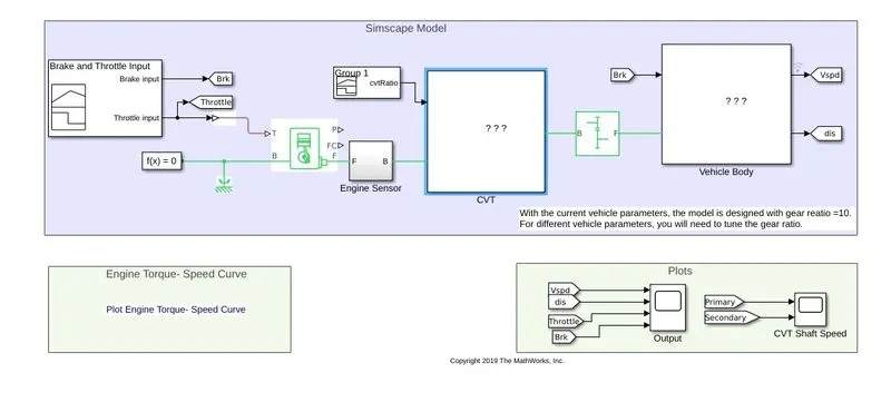
The image an atv with cvt is pasted above.
BLOCKS USED IN SIMULINK MODEL
SIGNAL BUILDER BLOCK: This block is used to provide values for throttle and brake .As from the model the input to the model are brake and throttle . The throttle input is for accelerating and on applying the brake input the vechicle will get retarded. Both the inputs i.e the throttle and brake is provided by signal builder block. By using signal builder the brake input is provide with a value '0' and the throttle input is provided with a value '0.5' The value from the throttle is feeded to the generic engine.
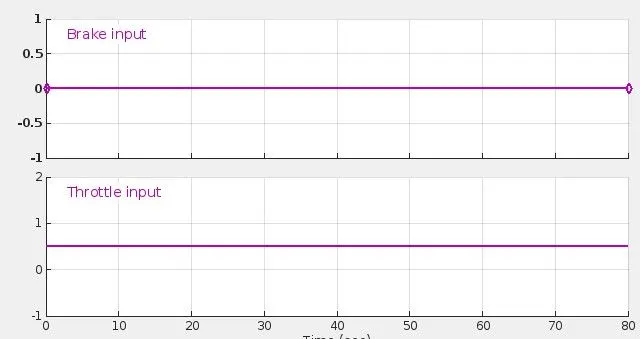
The image of signal provide by signal builder for throttle and brake is pasted below
FROM AND GO TO
This are used to plot the input value and output values to the scope
GENRIC ENGINE
Represents the system model of an internal combution engine and is suitable for modeling at the initial stage of model when basic parameters are available. The throttle value from signal builder is feeded to throttle port 'T' of the generic engine block.The throttle input signal 'T' lies between '0' and '1' and specifies the torque demanded from the engine as a fraction of the maximum possible torque.if the engine speed falls below the stall speed the engine torque is blended to zero.If the engine exceeds the maximum speed the simulation stops and issue an error message.Ports'F' and'B' are mechanical rotational conserving ports associated with engine crank shaft and engine block.Connections 'P' and 'FC' are signal output ports through which engine power and fuel consumption rate are reported
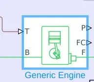
SIMULINK TO PS COVERTER
Used to convert the simulink signal to physical signal. Here it coverts the throttle input and feed it to the generic engine
SOLVER FUNCTION BLOCK
The solver function specifies the solver parameters that the model needs before starting the simulation
iDEAL ROTATIONAL MOTION SENSOR
Motion sensor with sensor name"SENSOR" is feed from the port 'F' of the generic engine which is one of the rotational conserving port associated with engine crank shaft.This sensor is used to records REVOLUTIONS PER MINUTE(RPM) and is named as RPM and gives a clear image of RPM of the model. The sensor is considered as IDEAL.
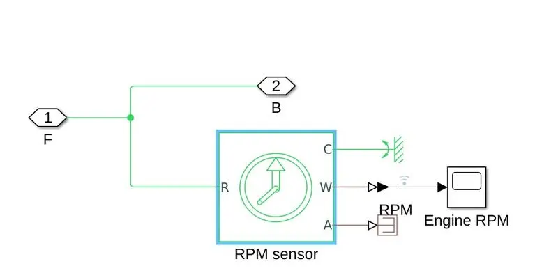
The physical signal ports 'W' and'A' report the angular velocity and angle. of port'R' relative to port'C'.The measured angular velocity is positive when the angular velocity at port R is greater than the angular velocity at port'C'. The port 'C' is connected to mechanical referance and port 'A' is connected to ps terminator
CVT
Is one of the transmission techanique which is used to transfer the mechanical power generated by the engine to the wheels. In this transmission techanic the main roles are played by two conical pulleys and they are connected by a steel belt.As we all know when we consider a gear there come the term"GEAR RATIO" and as it name indicate it gives the relation between input speed and output speed(i.e GEAR RATIO=OUTPUT SPEED/INPUT SPEED) here different gear ratio are adjusted by adjusting the diameter of input pulley(Din) and the diameter of outpulley (Dout). Initially Dout>Din, in this configuration the output speed will be less than the input speed. in order to achieve an overdrive condition the condition has to be Din>Dout and is done by adjusting the movement of cone shaped pulleys.
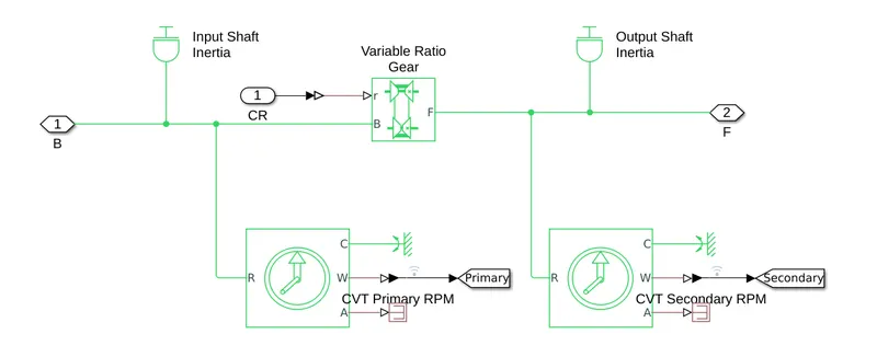
blocks used in cvt
(a) input shaft inertia and output shaft inertia:Both the block represents ideal mechanical rotational inertia.This block has one or two mechanical rotational conserving ports.The block positive direction is from its port to the reference point. This means that the inertia torque is positive if the inertia is accelerated in the positive direction
(b)rotational motion sensors:Two ideal rotational motion sensors are used to records the motion of shaft 1 or pulley 1 and motion of shaft 2 or pulley 2
(c)variable ratio gear: Represents a variable ratio gearbox such a implemented by mechanical belt CVT,electric, or hydraulic transmissions.The physical signal input r defines the ratio of input to output angular shaft velocities. Connections'B' (base) and "F"(follower) are mechanical conserving ports and specify the relation between base and follower rotation directions with the output shaft rotates parameter
SIMPLE GEAR BLOCK
On connecting the CVT block and the vechicle requires speed reduction for this the simple gear block is used.The block represents a fixed ratio gear or gear box.No inertia or compliance is modeled in this block.We can optionally include gear meshing , backlash and viscous bearing losses.
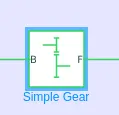
connections 'B'(base) and 'F' are mechanical rotational conserving ports.The port'B' is feeded by the output of CVT
VECHICLE BODY
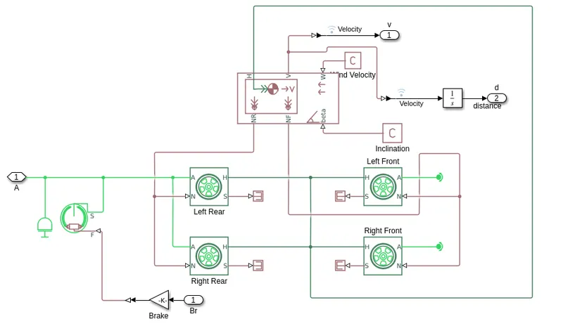
on going through vechicle body sub system block we can see the following blocks
(a)tire
four tire blocks are used for left front.left rear,right front,right rear. The block represents the longitudenal behaviour of a highway tire characterised by the magic formula.The block is buit from tire-road interaction and simscpe foundation library wheel and axle blocks. the rotational conserving port "A"of axle is connected to port"s" conserving rotational terminal associated with drum shaft of double-shoe brake block
(b)double-shoe brake
The block represents arranged as two pivoted rigid shoes symmetrically installed inside or outside a drum and operated by one actuator.The actuator force causes the shoes to excert a frictional torque on a shaft connected to the drum"F" is the signal port representing the force input to the actuator
(c)gain block
Gain block is used to provide the actuator or brake input multiplied before feeding to double shoe block
(d) vechicle body
represents a two axle vechicle body in longitudinal motion. The block accounts for body mass, aerodynamic drag,road incline,and weight istribution between axle due to acceleration and roadprofile.The vechicle can have the same or a differentnumber of wheels on axle.Optionally include pitch, suspension dynamics or additional variablr mass and inertia.
"H" is themechanical translational onserving port and is connected by the traction motion developed by tires.ports"v"nf" and nr are output ports for vechile velocity and front and rear normal forces respectively.ports"w" and beta are input ports corresponding to headwind speed and road inclination
INPUT AND OUTPUT OF THE ATV MODEL WITH CVT
INPUT
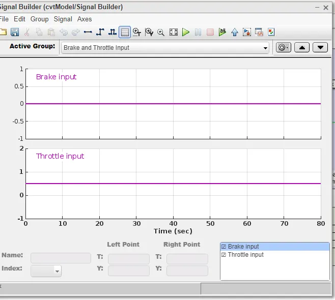
From the signal builder we can see that the throttle value is given 0.5 and the brake value is given as '0'
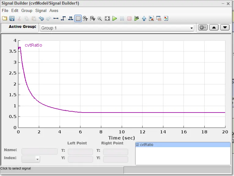
The above figure shows the signal provided to the CVT block as for Cvt gear ratio for attaining different gears
Output
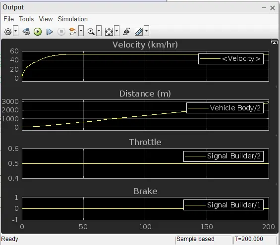
on examining the output for the throttle value '0.5' and brake input '0' the vechicle velocity increases and get almost to a stable value around '50' in 50 sec the distance also getting uniformly increasing with time
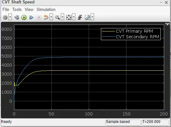
This figure shows the shaft speed of primary and secondary shaft of cvt. On examing we can see that the seconadary shaft attains high rpm than the primary shaft for the barke '0' condition and overdrive condition is achieved
CASE 2
SIMULINK MODEL OF BAJA ENGINE USING DASHBOARD BLOCKS
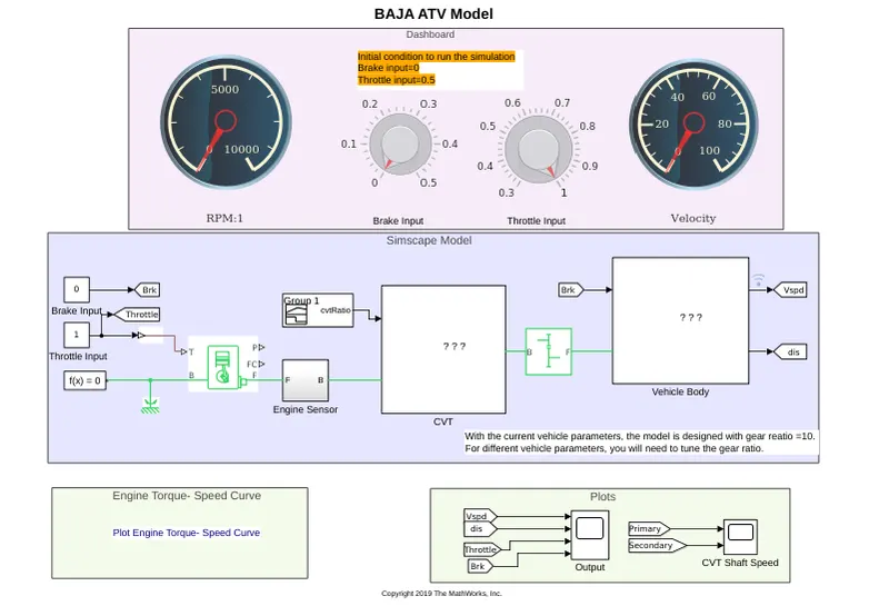
In this image we can see that the simulink model is incorporated with dashboard library blocks. The additional blocks used are
!) two constant blocks: In order to connect the dash board block (knob ) throttle and brake are provide with two constant blocks. The throttle is provided with a constant block with value '1' and brake is provided with constant block '0'.
NOTE: using this dashboard block knob and putting simulation time equals to infinity(inf) we can change the value of throttle and brake during simulation and can plot the output velocity at that time
2) two guage block: One dashboard block guage is connected with engine sensor and will show the Rpm during the simulation and the other is connected with vechicle body through which can examine the vechicle velocity during simulation
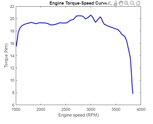
The above image shows the torque speed curve of BAJA atv. from the figure we can see that the torque decreases after 3000 rpm and terminates at around 3800 rpm. This data is feeded to the generic engine
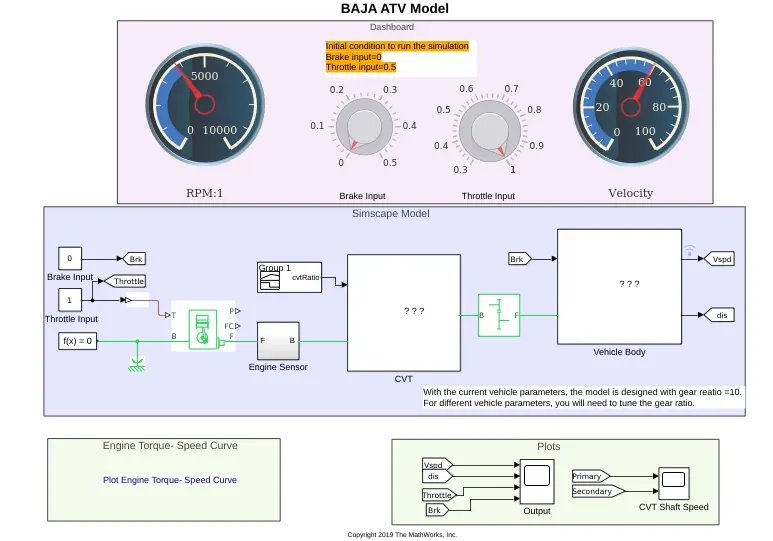
providing throttle input'1' and brake input'0' we get the following output on rpm guage and velocity guage. On increasing the brake input we can see the rpm and velocity represented by the guage approch zero the image is pasted below
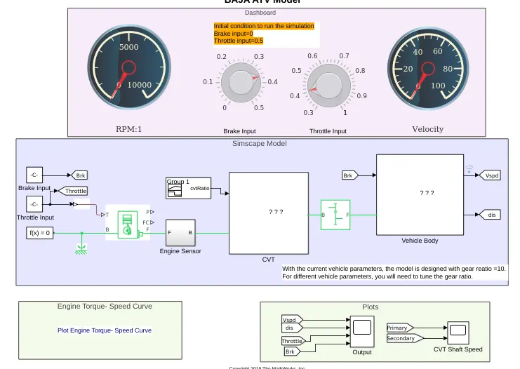
Input and output characteristics of open loop model
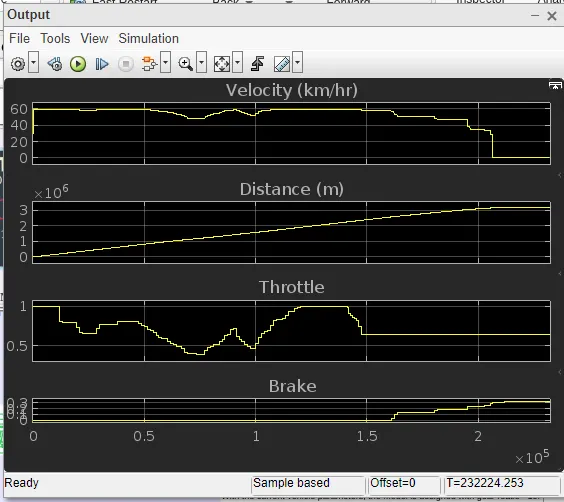
On observing the scope image we can see that the velocity of the vechicle is linearly proportional to the throttle input. the distance graph shows a uniformly increasing nature and when the brakeinput is increased after 1.5 sec we can see that the velocity of the vechicle is decreasing
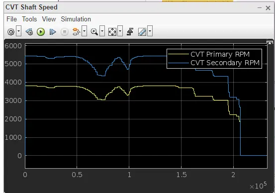
initially we can see that the secondary shaft rpm shows a higher value since the simulation started by providing throttle input as 1 and after applying the speed we can see that the speed of the secondary shaft is decreasing ie the velocity decreses since the output is taken from the secondary shaft
case3
In the above two models we are giving random value to cvt ratio and checking the vechicle perfomance. but this not comes true because the cvt ratio depends upon the velocity of vechicles so we are providing thcvt ratio feeded from velocity of a the vechicle and this model is called a closed loop model and the other two models are called open loopmodel
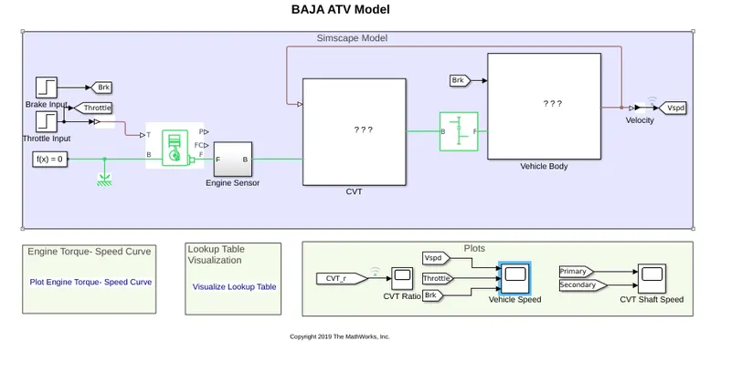
The above image is similar to case 1 but the difference is that in case one there we had no feedback.ie case1 is an open loop model and case 3 is the closed loop model and the other thing to be noted is that in this model step iput is given for throttle and brake input.
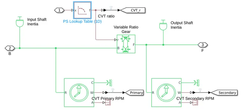
on opening the cvt system we can see that the cvt ratio is provide through lookup table
INPUT AND OUTPUT OF CLOSED LOOP WITHOUT DASH BOARD
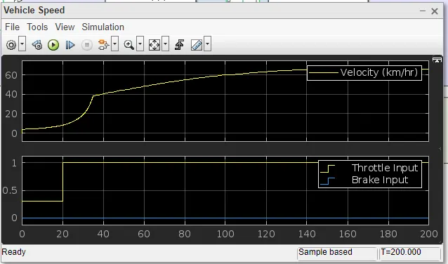
On seeing the image of input and output fron the scope we can see that for brake input '0' and on increasing the throttle input towards one the velocity of the vechicle increases
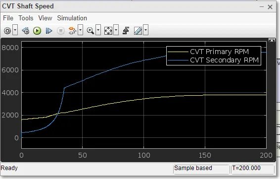
on observing the shaft speed output scope we can observe the same situation that on increasing the throttle the speed of secondary shaft is increasing and the vechicle reaches overdrive condition
case4
The image of the closed loop model with dash board is pasted below.
here in the below shown image we can see that the throttle and brake input can be change by adjusting the knobs during simulation and the corresponding value will be reflected on the respective guages
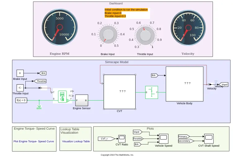
In this model we can see thath the velocity is feeded to cvt block. on opening the cvt subsystem we get the following details
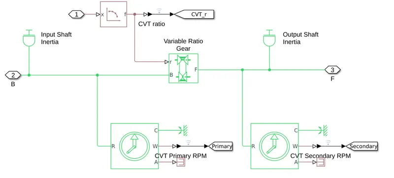
here we can see the lookup table. and from the data of lookuptable the cvt gear ratio is calculated
input and output of closed loop model with dash board
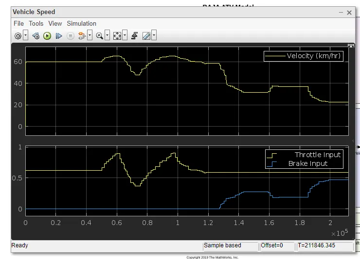
on observing the image we can see that on varying the throttle the velocity of the vechicle is increasing and decreasing. and after 1.2 sec just observe that when i had increased the brake input the velocity of the got decreased and approching around 20
RESULT
The following models are simulated and the outputs from the scope are observed
Reference
(1) youtube
(2) mathworks
(3)chaitra(skill lync)