Week - 4
Solution for Question 1:
Steps:
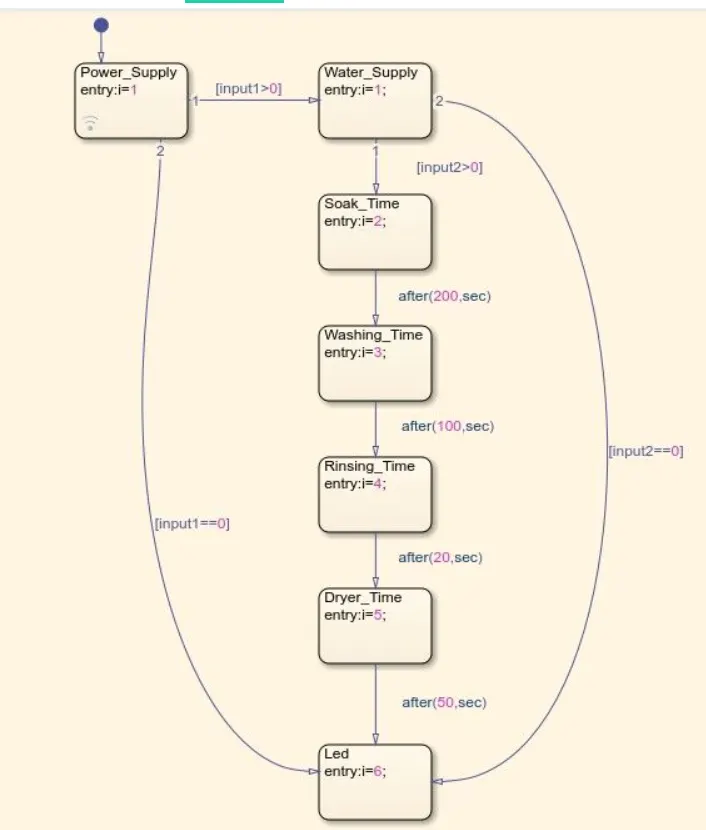
1. To run the given sequence operation of washing machine , we need to create a STATE FLOW chart to perfor the operation with respect to time.
2. As per the given condition, if the power supply is available the system gets activated. To start the machine we need to provide an input signal using a constant block with value as 1 defines the ON state and 0 defines the OFF state.
3. For water supply also , we need to provide a constant block to tell the circuit about it's state.
4. To perform all operations , we need to assign the delay after each stage using AFTER logic.
5. A lamp block is added to displaay all the operation and each colour is assigned to each individual state . By varying the simulation time , we can check the LED colour.
6. A display is attached at the output to show the time step, Also by changing the value of constant for power supply we check the logic by the change of the LED signal lamp.
7. Simulation RUN time for this logic is 500.
Blocks used:
- Constant
- Chart
- Scope
- Lamp
Simulink Chart layout:
Flowchart for the operation sequence is as shown below
Simulinkc circuit layoit is shown below:
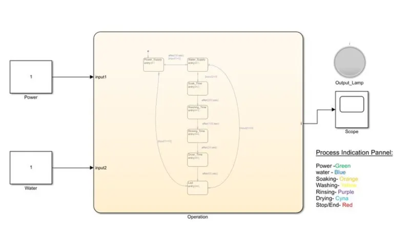
LED colours code:
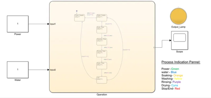
Power - GREEN
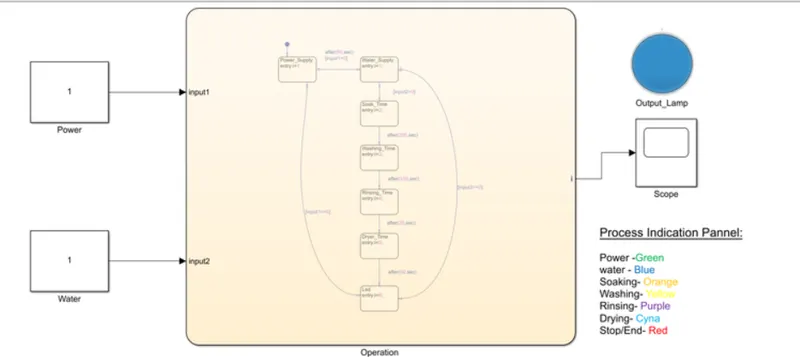
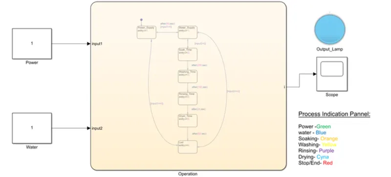
Water - BLUE
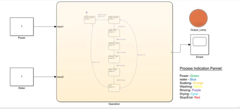
Soaking - ORANGE
Washing - YELLOW
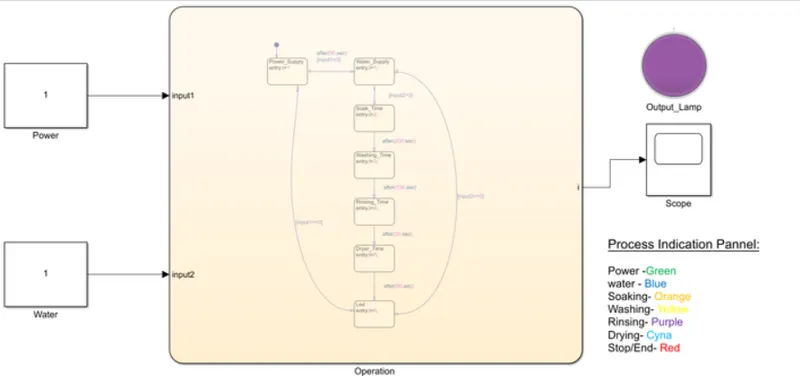
Rinsing - Purple
Drying - Cyna
Stop/End - RED
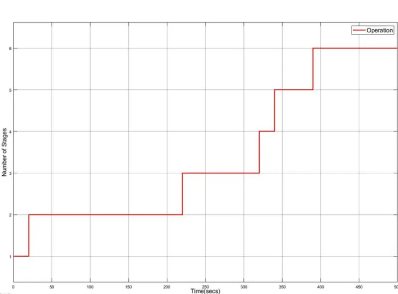
Operation Stages:
1. Water supply is available
2. Soaking
3. Washing
4. Rinsing
5. Drying
6.End
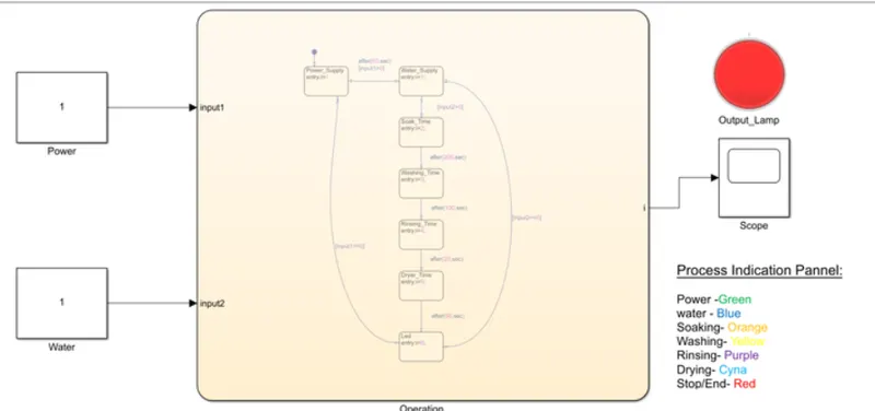
RESULT:
The Time Step of WASHING MACHINE operations is plotted below
Solution for Question 2:
GEAR SHIFTING
Steps:
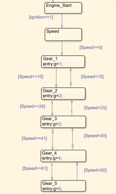
1. A chart block is created to perfor the gear shifting by using the logic of 'greater than equal to' and 'less than equal to', so that we display the gear shift number as per the speed on the speed on the speedometer.
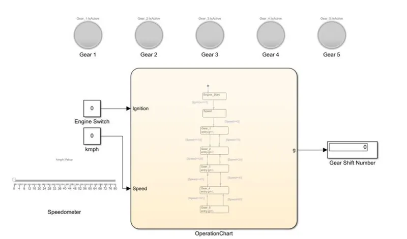
2. A logic is created for each stage as per the given speed range. A constant block is provided to ON the engine and a display block to show the present GEAR number.
3. Slider block is used as a speedometer linked to a constant block to assign the values of speed.
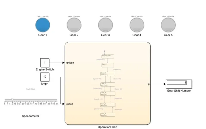
4. By changing the speed, we can check the gear shift number on the display blocl. Also, lamp blocks are linked at each stage of the gear shift to show the gear position with respect to the speed given.
5. Simulation RUN time for this logic is 80.
Blocks used:
- Constant
- Chart
- Display
- Slider
- Lamp
Flow chart for Gear shift logic:
Main Simulink circuit layout:
Gear Shifting stages:
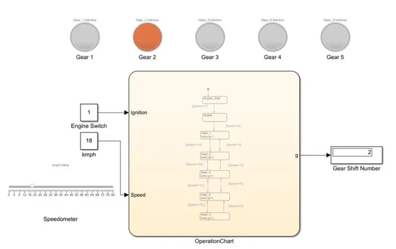
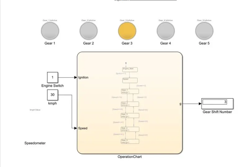
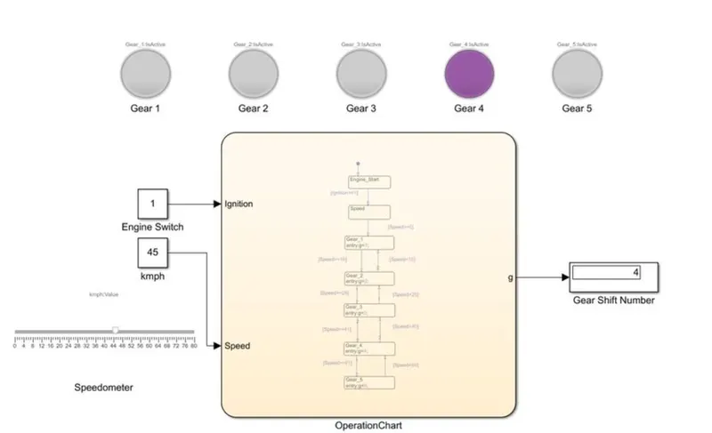
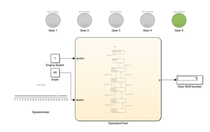
Below figures shows the gera shifting with display of the gear number with respect to speed with each individual lamp turning ON.
1. Gear shift 1 indicator
2. Gear shift 2 indicator
3. Gear shift 3 indicator
4. Gear shift 4 indicator
5. Gear shift 5 indicator
CONCLUSION:
Successfully created the simulink block diagram for the simulation of washing machine using the given sequence and gear shift with the display of the gear number with varying speed limits using LED lamps.