Week -2
Solution for Question 1:
Aim:
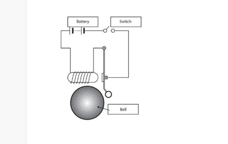
Designing a Simulink model of Doorbell using a Solenoid Block.
Schematic Diagram:
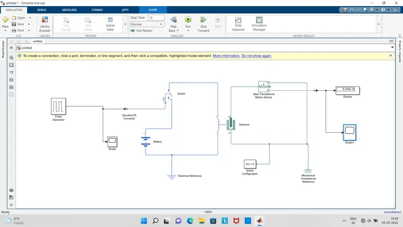
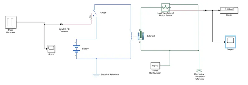
Simulink Model:
Blocks used:
- Pulse Generator
- Simulink-PS converter
- Switch
- Battery
- Solenoid
- Electrical reference
- Ideal Translational Motion Sensor
- Solver Configuration
- Mechanical Translational Reference
- PS-Simulink Converter
- Display
- Scope
Explanation:
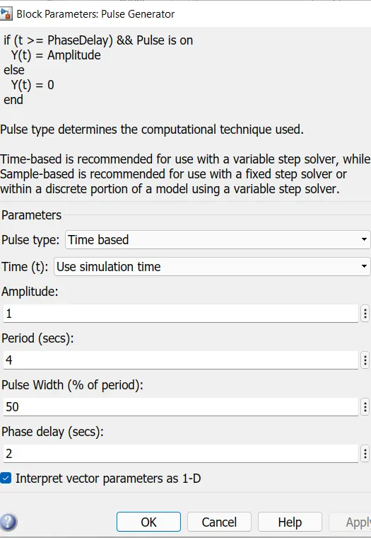
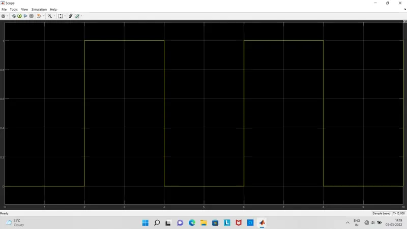
- Pulse Generator produces the Pulse Signals at Regular Intervals. Here the the signal has amplitude 1 , Period of 4 Seconds , Pulse width 50 and with a phase delay of 2 Seconds.
- The Switch Block is controlled by external physical signal,if the external signal is greater than the Threshold parameter then the switch is closed otherwise it is open.
- One terminal of switch is connected to the Battery positive , another terminal is connected to the Solenoid positive and further connected to Electrical Refernce(Grounding)
- Solenoid is the ELECTRO MAGNETIC DEVICE with wire winding on a Metal Peice. When the current flows in the wire an electro magnetic field is developed.
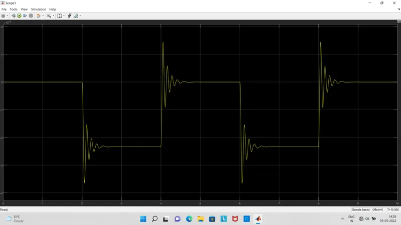
- The Ideal Translational Sensor P is connected to the Display as well as Scope because we need to Show the POSITION.
- Solver configuration is Mandatory here because we are using simscape blocks in this Model, for successful Operation of model we are including solver configuration.
Results:
Output of PULSE GENERATOR: This is how the PULSE signals are generated by the PULSE GENERATOR.
SCOPE: With the help of Scope we can Observe the DOORBELL ringing for every 2 Seconds as Shown Below.
Solution for Question 2:
Aim: Designing a Simulink model to Operate Fan with use of a Thermistor to sense temperature of Heater.
Condition: Fan has to TURN ON if the temperature is above 25 Degrees Celcius.
Simulink Model:
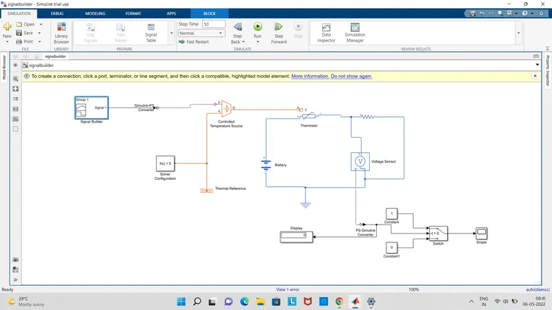
Description:
Thermistor:Thermistor is a semiconductor Temperature dependent variable thermal resistor that changes it's resistance with Temperature. Thermistor is combination of words THERMAL and RESISTOR. Technically, all resistors are thermistors as their resistance changes slightly with temperature but the change in these resistors are usually very small as compared to thermistor.
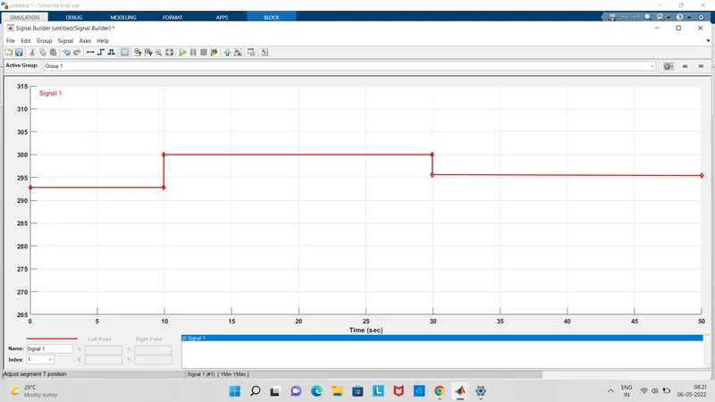
Signal Builder: This block allows you to create interchangable groups of peicewise linear signal sources and use them in a model. For a quick switching of signal groups into and out of a model to facilitate testing in the Signal Builder , produce signals and define the output waveforms.
Controlled Temperature Source: It represents an ideal source of thermal energy that issufficient to maintain secified temperature difference across the source with out considering heatflow consumed by system.
Voltage Sensor: The voltage sensor block represents an ideal voltage sensor, that is a device that converts voltage measured between two terminals of an electrical circuit into a physical signal proportional to thr volatge.
Switch: Switch block passes through the first input or the third input signal based on the value of the second of input.first and third are data inous and second input is a control input .
Solver configuration: Each physical network represented by a connected Simscape block diagram requires solver settings information for simulation.it specifies the solver parameters that model needs before simulation start.
Battery: Positive terminal is connected to Thermsitor and negative is connected to electrical reference.
RESULTS:
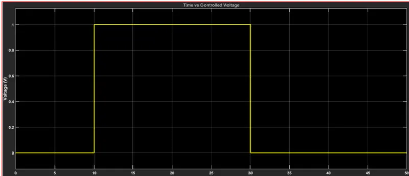
As shown below the fan wii get Turn ON when the temperature exceding 25 degrees celcius , we have time period of 50 seconds , in this from 0 to 10 seconds temperature is 20 degrees celcius so fan is OFF condition, next from 20 to 30 sconds temparature is 27 degrees celcius so the fan is in ON condition and then from 30 to 50seconds temparature is 23 degrees celcius so the fan is in OFF condition.
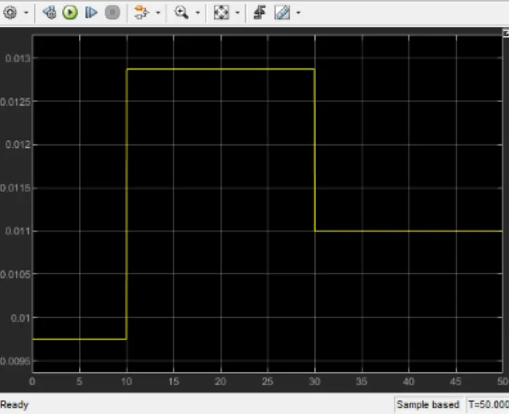
Below graph the voltage across FAN according to the ON and OFF conditons based on the TEMPERATURE.
CONCLUSION: Hence model is designed for FAN operation using a thermistor according to the conditions mentioned in the question.