Week - 4
Aim:
Implement control logic of a “washing machine” using Stateflow as per given sequence
Given condition of Washing machine stateflow:
- If the power supply is available, the system gets activated
- If the Water supply is not available, stop the process & indicate through LED
- Soaking time should be 200s followed by Washing time of 100s.
- Then rinsing happens for next 20s & dryer runs for 50s
State flow:
State flow provides a graphical language that includes state transition diagrams,flow chat,state transition tables and truth tables. Its used to describe how MATLAB algorithms and Simulink models react to signals,events time based condition. Its enables design and develop supervisory control, task scheduling, fault management ,communication protocols,user interface and hybrid system.
Control logic:
It’s a key part oa a software program that control the operation of the program. Control logic reponds to commands from the user and its also act on its own to perform automated taks that have been structured into the program. Model using state diagram .
Procedure :
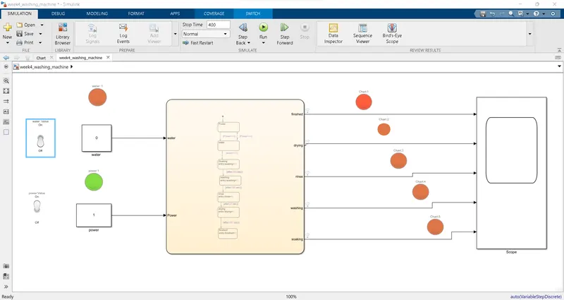
- Input, power,water supply are connected to the chart through slider switches by initiating constant values 0 and 1 condition ON and OFF. Flow process initiated as per the given condition.
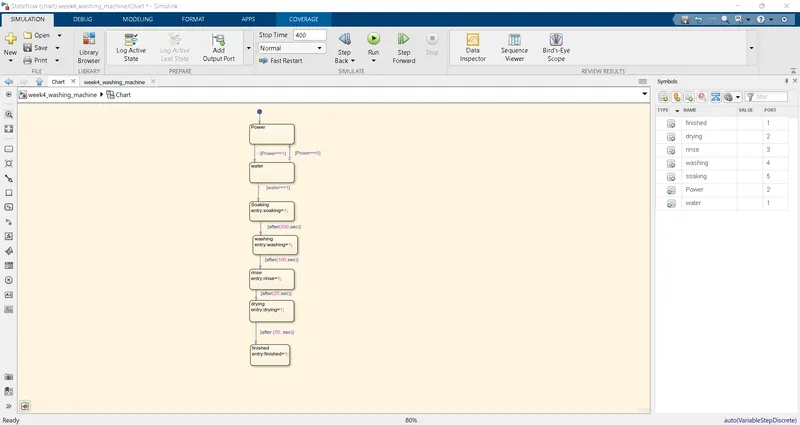
- Flow-1: power ,water supply -checking water supply if power is ON-filling water if water supply ON-soaking-washing-rensing-drying-finish.
- Flow-2: power & water supply -checking water supply if power is ON-no water if water supply if OFF-finish.
- Using junction box will repeact the process after finish/end
- If condition is stratified the LED show a green color,elsa a red color.
chats:
If[1 0]:
when the only power source is ON & water supply s OFF.water supply is OFF the flow will get terminate after checking the water supply and then the process gets END.
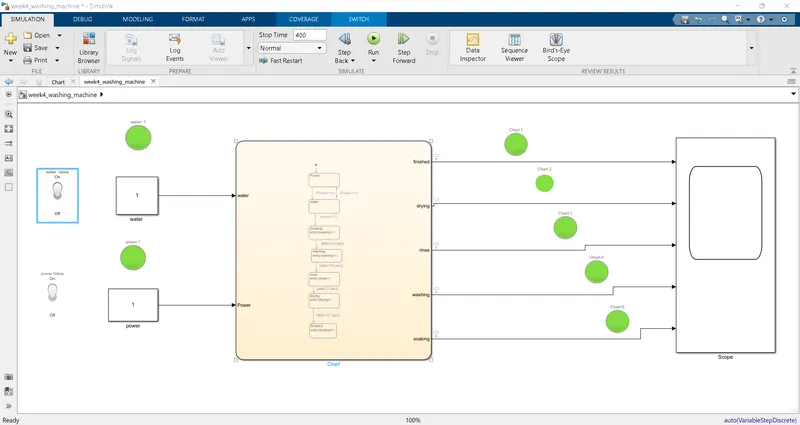
If[1 1]:
After all the process have completed turn on the finished LED.
Explanation:
- We going to design the mode of washing machine to run in the condition given.so 1st we have to design a stateflow of the washing machine with some process are power,water,soaking,washing,rinsing,drying and finish.
- Use Chat block to construct the stateflow .its fully construced by 0 and 1 value. and then 1 and 1 values.
- Use the connects all the electrical functioning process to power by transition line through the junction . after the design of each blocks stateflow apply the given condition as run. Each process as the set amount of time.(from a given data's).
- Now exit from the stateflow and given two inputs (power, water)using constant block and connect those block with lamp.
- Then connects all the output of 7 process from the state flow to scope separately. Add more lamp to connect with scope of output to check the final process.
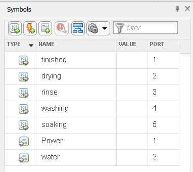
- program run check the port number in symbols pane on the stateflow .which in toolstrip bar
symbols :
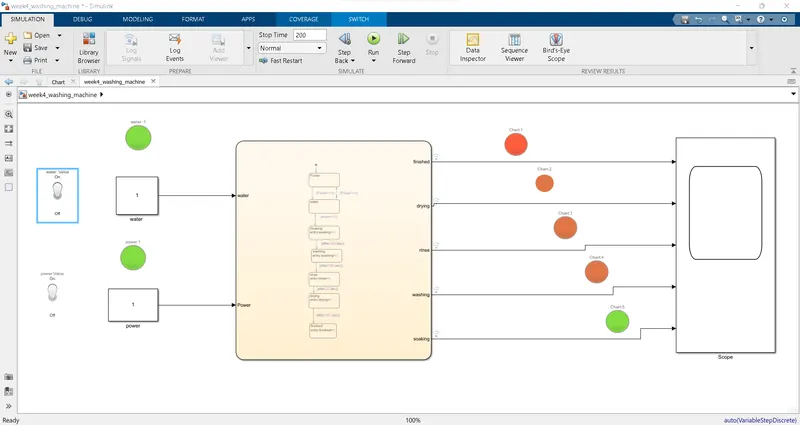
- Soaking time should be 200s followed
 S
S
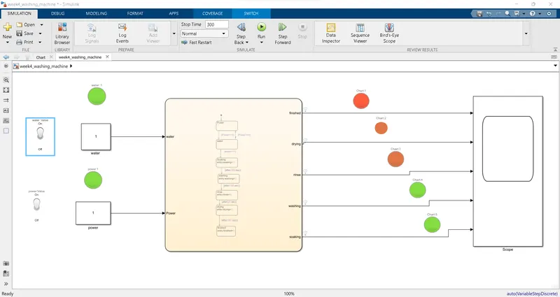
Washing time of 100s followed
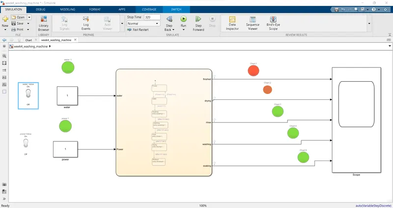
rinsing happens for next 20s
dryer runs for 50s
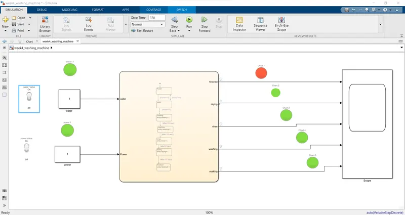
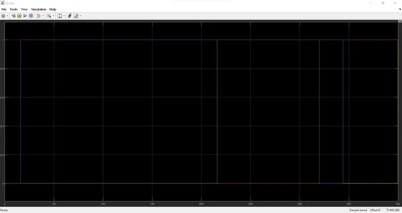
scope final results are:
2. Make a Simulink chart for the “Gear shift” logic as per below conditions:
Speed Range(kmph) Gear
0 to 15 1
16 to 25 2
26 to 40 3
41 to 60 4
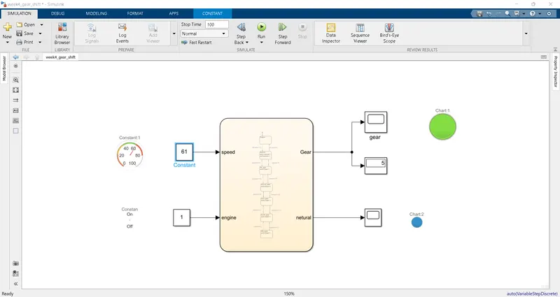
Above 61 5
explanation:
we going to design the model of gear shift to run in the certain condition as given.
we have to design a stateflow of the gear shift with 5 gear transmisson.
use the chart block to construct the stateflow .its fully constructed by the 0 and 1 value.
state option to construct the each process of the gear shift the n connects all the blocks through the transition line.
after the design of each block in state flow apply the given condition as run the each process in the amount of speed.
exit from the stateflow and given input of vehicle speed using constant block and connect that block with slider to control the vehile speed.
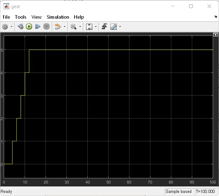
connects the output of G-gear from stateflow to display respectively and also connect the scope with output to analyza the input and output.
use 5 lamp block and connect all those in stateflow block for the indication of gear position
then set all gear lamp indicators the position of the gear by order.
finally set the stop time ,the program run and check the port number in the symbols pane on the staeflow which in the toolstrip bar
stateflow chat of gear shift & symbols are :
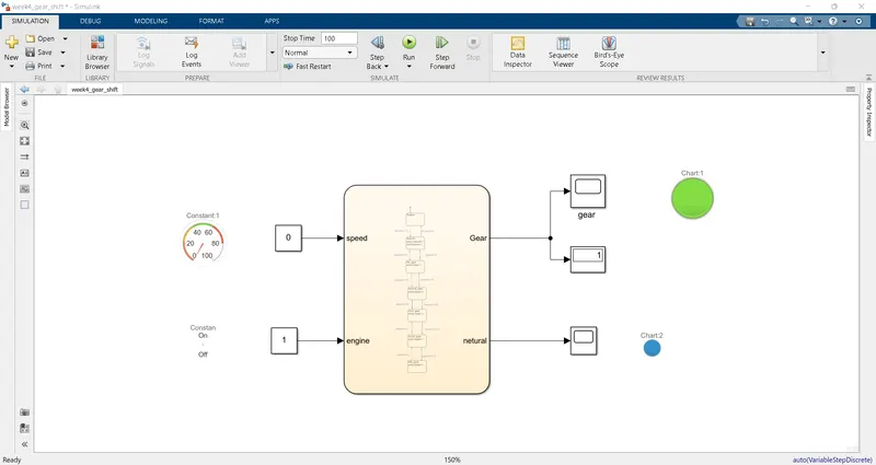
when engine speed 0-15 (km/h):
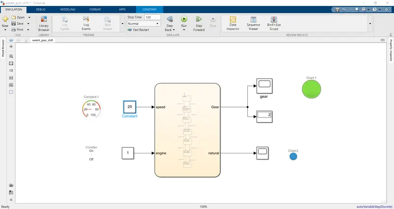
when engine speed 16-25 (km/h):
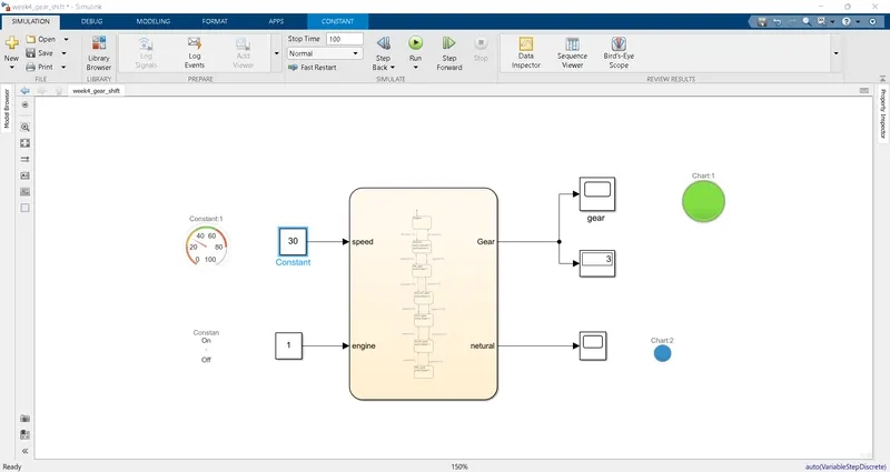
when engine speed 26-40 (km/h):
when engine speed 41-60 (km/h):
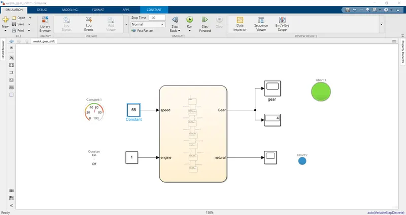
when engine speed 61 (km/h) above:
scop of output :
CONCLUSION:
as per the given condition both models achieved thier solution..
this model design the working of stateflopw concept has learned successfully.
well aware of the uses of lamp and slider block.