Week - 4
Question:
- Implement control logic of a “washing machine” using Stateflow as per given sequence:
- If the power supply is available, the system gets activated
- If the Water supply is not available, stop the process & indicate through LED
- Soaking time should be 200s followed by Washing time of 100s.
- Then rinsing happens for next 20s & dryer runs for 50s
After all the processes have completed turn on the finished LED
2. Make a Simulink chart for the “Gear shift” logic as per below conditions:
Speed Range(kmph) Gear
0 to 15 1
16 to 25 2
26 to 40 3
41 to 60 4
Above 61 5
Give speed input while the simulation is running & display the gear number.
Aim:
-The first project has aim to familiarise with the state flow and of automatic processes. To get to now more o the control processes of machines like a washing machine.
-For the second challenge we still getting to familiarise control of atomatic processes and state flow. In this case we will be looking at the shift in gears of a gear box.
Answers:
1) What is a washing machine:
A washing machine (laundry machine, clothes washer, washer, or simply wash) is a home appliance used to wash laundry. The term is mostly applied to machines that use water as opposed to dry cleaning (which uses alternative cleaning fluids and is performed by specialist businesses) or ultrasonic cleaners. The user adds laundry detergent, which is sold in liquid or powder form, to the wash water.
A wash mashine has different washine modes, it washes based on the selected mode. The user hast to put and amount of detergent in the machine but the amount of water and amount of detergent used for washing under a particular mode is automaticaly taken by the machine.
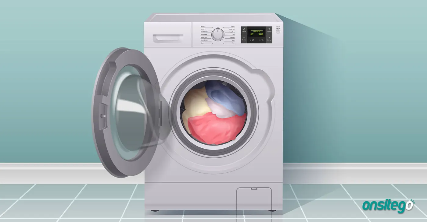
A washine machine follows the following steps for each washing circle.
-Prewashing
-Washing
-Rinsing
-Drying
For different washing mode, different time will be alocated to the above mentioned steps and the clothes are washed at a particlar water temperature based on the washing mode.
Simulation:
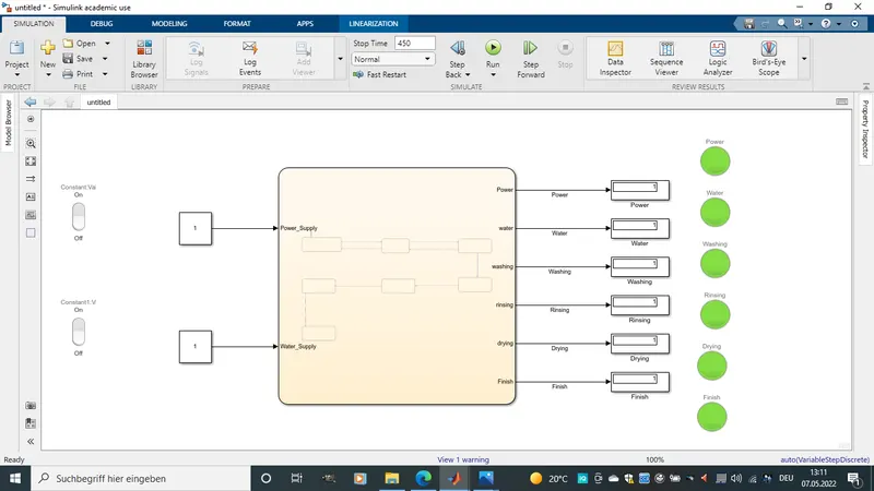
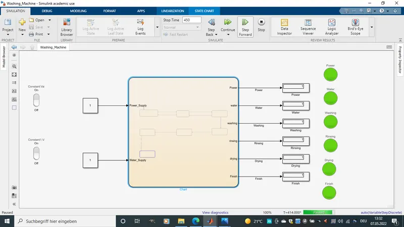
The model is as shown above.
-Two switches to switch on the washing machine and to select washing mode so that clothes get soaked.
-Six lamps are used to indicate each of the states of power, soaking, washing, rinsing, Drying and to indicate the end of the washing processes.
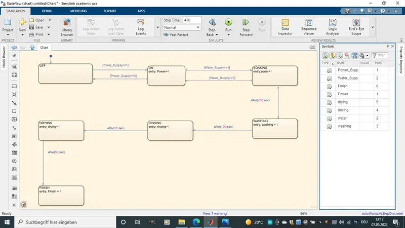
-Below is an image of the state flow chart.
Lamp:
The Lamp block displays a color to indicate the value of the input signal. You can use the Lamp block with other Dashboard blocks to build an interactive dashboard of controls and indicators for your model. You can specify pairs of input values and colors to provide the information you want during simulation.
Rocker Switch:
The Rocker Switch block toggles the value of the connected block parameter between two values during simulation. For example, you can connect the Rocker Switch block to a Switch block in your model and change its state during simulation. Use the Rocker Switch block with other Dashboard blocks to create an interactive dashboard for your model. Double-clicking the Rocker Switch block does not open its dialog box during simulation and when the block is selected. To edit the block's parameters, you can use the property Inspector , or you can right-click the block and select Block Parameters from the context menu.
Reslut:
-For the reslt, the washing machine will be simlated stepwise to show the change in washing state after the apropreat time.
-At the begining of the simulation all lamps are off. the simulation time could be seen below as 00.00
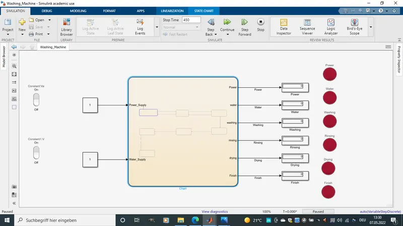
-9 sec after the power of the machine is trned on.
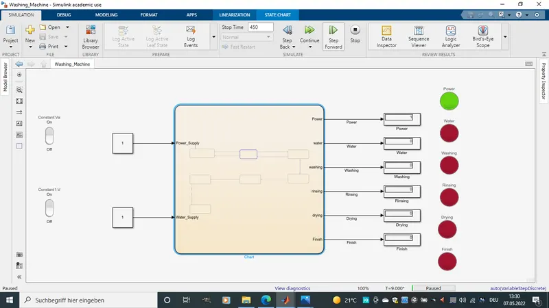
-18 sec after the clothes beging to get soaked.
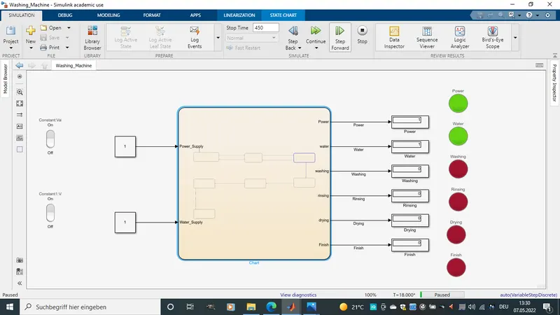
-200 sec after clothes are all soaked now washing starts.
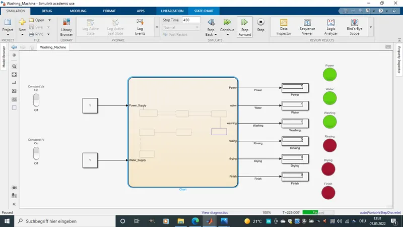
-100 sec after the clothes are washed now the Rinsing begings.
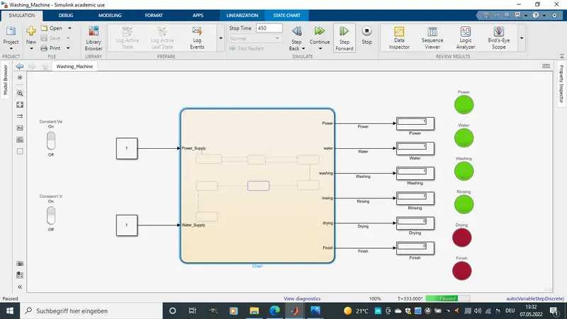
-20 sec after the Rinsing process is over and the machine starts drying them off.
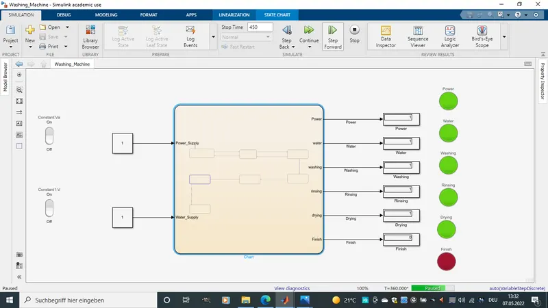
-50 sec later the clothes are dryed and the washing process is over.
2) What is a Gear Transmission:
The most common type of automatic transmission uses hydraulic power to shift gears. According to How Stuff Works, this device combines a torque or fluid coupling converter with gearsets that provide the desired range of gears for the vehicle. A TCU in a modern automatic transmission generally uses sensors from the vehicle, as well as data provided by the engine control unit (ECU), to calculate how and when to change gears in the vehicle for optimum performance, fuel economy and shift quality.
Lamp:
The Lamp block displays a color to indicate the value of the input signal. You can use the Lamp block with other Dashboard blocks to build an interactive dashboard of controls and indicators for your model. You can specify pairs of input values and colors to provide the information you want during simulation.
Rocker Switch:
The Rocker Switch block toggles the value of the connected block parameter between two values during simulation. For example, you can connect the Rocker Switch block to a Switch block in your model and change its state during simulation. Use the Rocker Switch block with other Dashboard blocks to create an interactive dashboard for your model. Double-clicking the Rocker Switch block does not open its dialog box during simulation and when the block is selected. To edit the block's parameters, you can use the property Inspector , or you can right-click the block and select Block Parameters from the context menu.
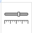
Slider:
The Slider block tunes the value of the connected block parameter during simulation. For example, you can connect the Slider block to a Gain block in your model and adjust its value during simulation. You can modify the range of the Slider block's scale to fit your data. Use the Slider block with other Dashboard blocks to create an interactive dashboard to control your model.
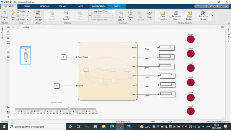
Simulink:
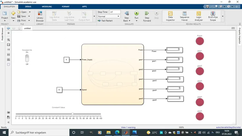
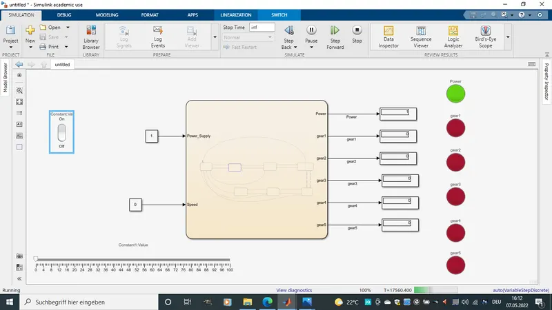
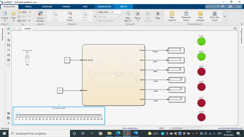
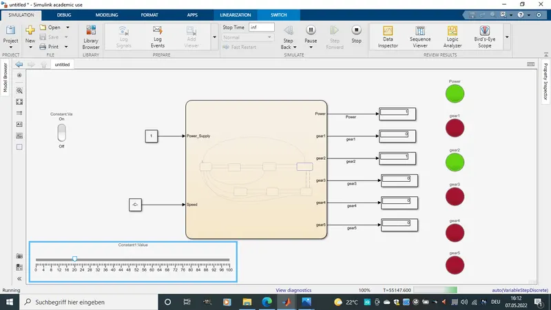
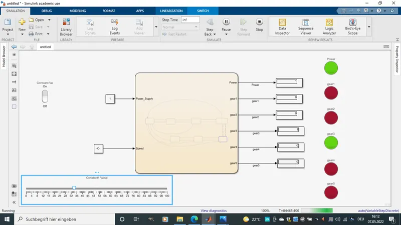
-The model is as shown above, When power is turned off all lamps are red and there will be no respond or shift in gear dispite speed input. Dring driving if power is switched off the vehicle stoppes and there will be no shift in gear dispite acceleration.
-The state flow is programmed as showen below.
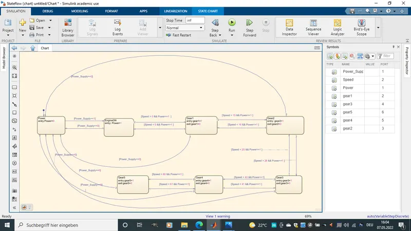
-The simulation will we started and the time for simulation is inf so that we have enough time to simulate the various speed difference and off and On of motor.
Results.
*Below is the picture of the simlation when simlation is started and engine is swited on.
*Below are pictures of gear shifting.
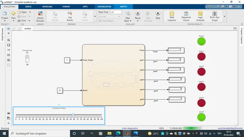
*Here is a picture of power switch during simulation. we notice the all lamp switch off as soon as power is switched off.