Week - 4
AIM: MODAL OF WASHING MACHINE USING STATEFLOW WHILE IMPLEMENT CONTROL LOGIC.
DESCRIPTION
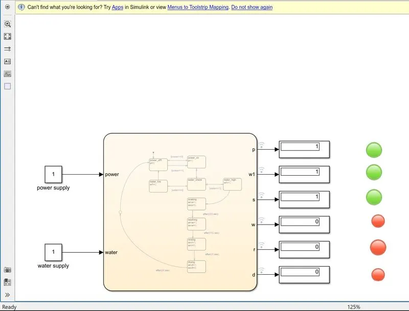
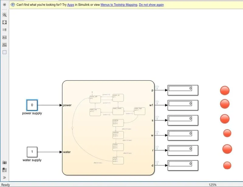
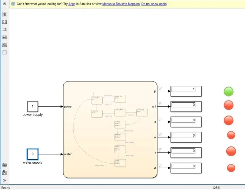
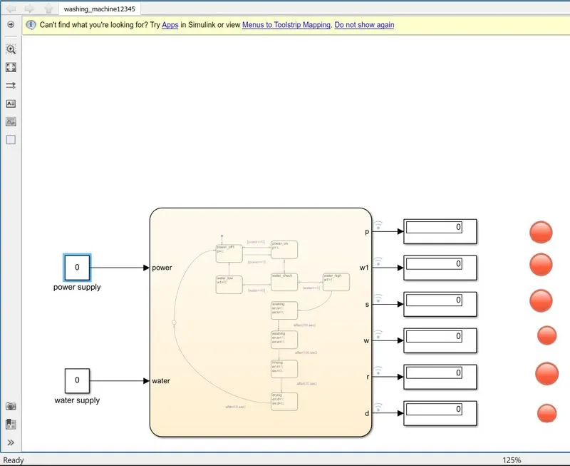
Lgic for washing clothes in washing machine is depend upon two condition.
1. power supply
2. water supply
Achieving one condition is not enough for drive washing machine. there should be availability of both condition.After getting power and water process of washing is further proceed in folllowing manner.
:SOAKING- For the process of soaking it requires 200 second.After 200 sec washing process is required to begin.
:WASHING-Washing is done after getting fullfill of conditon of 200 sec and access having washing for 100 second.
:RINSING- According to conditon achieved process of rinsing is begin and process of rinsing is being continue fo last 20 second.
:DRYING-Drying takes 50 second as per condtion applied.As all process done it enters action and leaves completed state.When leaving completed state it transmitted to off state.
SIMULINK BLOCK
1:SIGNAL BUILDER
2:CHART
3:LAMP
4:DISPLAY
5:CONSTANT
LAMP
IT is used for supply of water power and indication of state of machine. There is differnt color for active and inactive process such as green for procees being active and red for process being stop.
DISPLAY
IT helps in making sure of what process is being processing with the help of lamp.
constant
Constant act as on and off switch whatever directon is applied as per of signal using such as 1 and 0.
CHART
Chart is the graphical representation of states and transition.Such as on & off ,washing soaking, rinsing ,drying and complete state.
SIGNAL BUILDER
The signal builder gives the signal to the chart. Power supply water supply is active as per by signal builder. All the process soaking washing rinssing drying all are done with help of signal builder.
RESULT
After such calculation we get the accurate result submitting the simulink model.Thus control logic of washing machine using state flow is performed.as shown above.
_------------------------------------------------------------------------------------------------------------------------------------------------------------------------------------------------------------------------------------------------------------------------------------------------------------------------------------------------------------
GEAR SHIFT
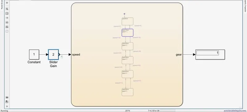
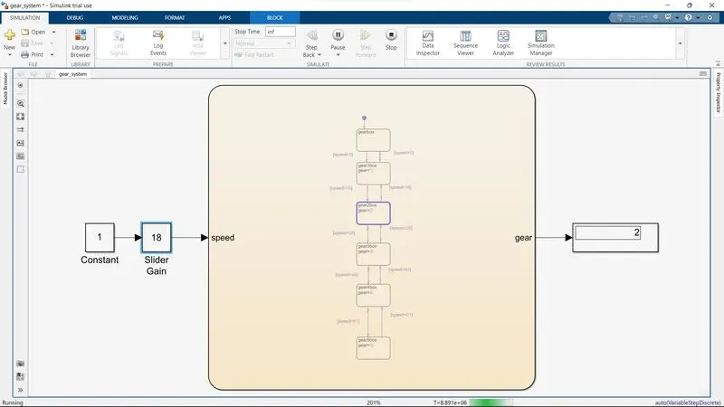
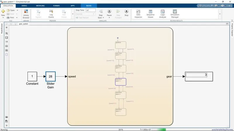
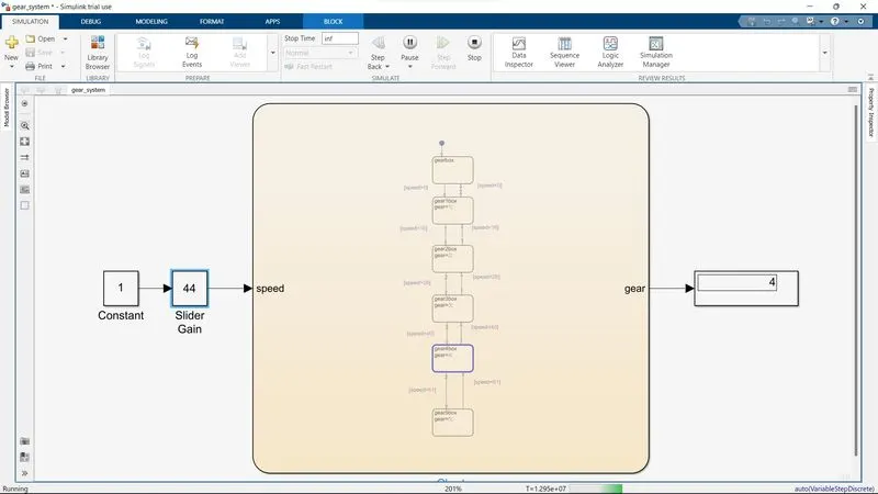
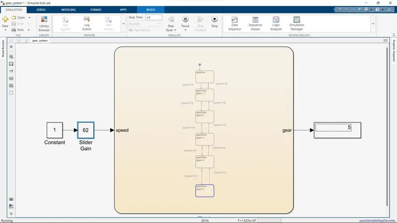
AIM: TO MAKE A SIMULINK CHART FOR GEAR SHIFT LOGIC USING STATE FLOW.
SIMULINK BLOCK
1:SIGNAL BUILDER
2:CHART
3:LAMP
4:DISPLAY
5:CONSTANT
6:SLIDER GAIN
LAMP
IT is used for supply of water power and indication of state of machine. There is differnt color for active and inactive process such as green for procees being active and red for process being stop.
DISPLAY
IT helps in making sure of what process is being processing with the help of lamp.
constant
Constant act as block to give the constant value to the model over the simulink time.It comes with prblock determine constant.It is used with slider gain bgain value be constant.
CHART
Chart is the graphical representation of states and transition.Such as on & off ,washing soaking, rinsing ,drying and complete state.
SIGNAL BUILDER
The signal builder gives the signal to the chart. Power supply water supply is active as per by signal builder. All the process soaking washing rinssing drying all are done with help of signal builder.
SLIDER GAIN
It is used to slide the value during simulation is running .This value is connected to the custom guage.the value is varying from 0 to 100.
RESULT
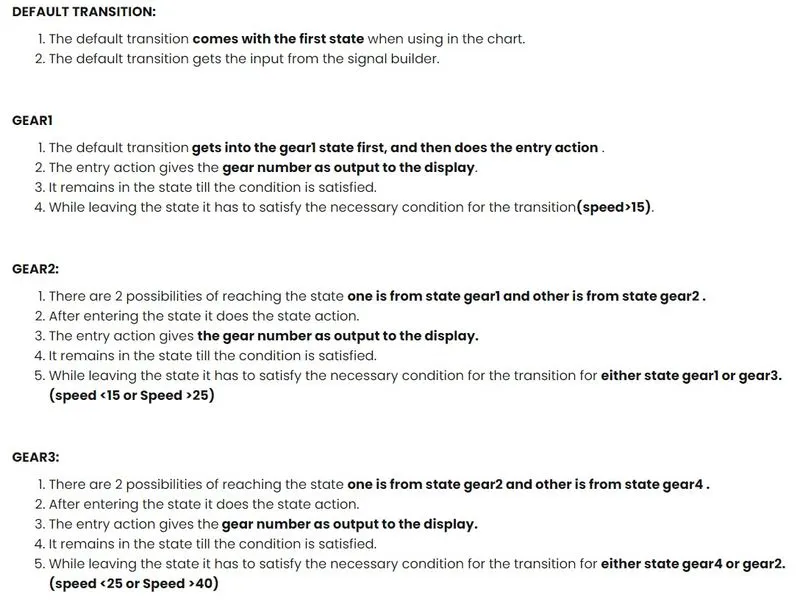
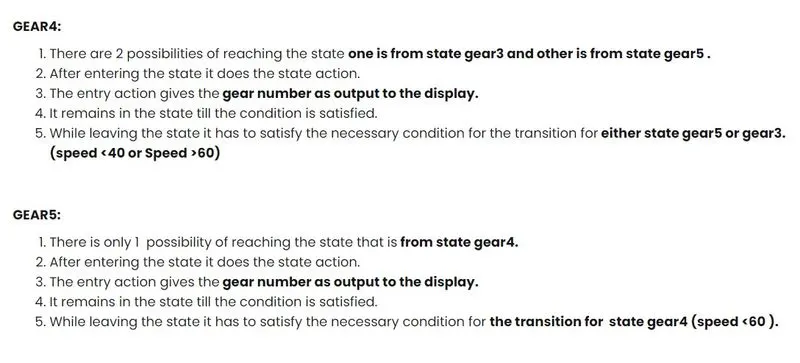
After performing various calculation the simulink model is submitted to give the accurate result. Thus the simulink chart for the gear shift logic .
LEAVE A COMMENT
Thanks for choosing to leave a comment .Please keep in mind that all comments are moderated according to our comment policy and your email addressse will not be published . Lets have a personal and meaningful conversation.