Week - 4
QuestionNo.1:
- Implement control logic of a “washing machine” using Stateflow as per given sequence:
- If the power supply is available, the system gets activated
- If the Water supply is not available, stop the process & indicate through LED
- Soaking time should be 200s followed by Washing time of 100s.
- Then rinsing happens for next 20s & dryer runs for 50s
Aim:
To design a washing machine with above configuration in stateflow model.
State flow diagram:
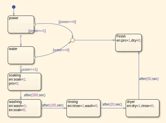
Fig.1.stateflow chart.
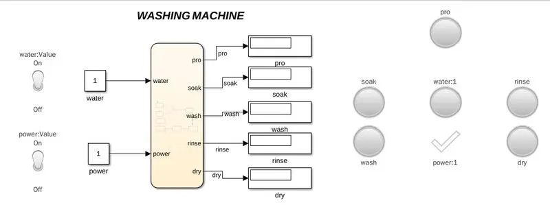
Fig.2.simulink model.
Procedure:
- In first state power we assigning our input and checking whether washing mc is ready to operate with continuous power supply.If power==0 then there is no power supply so,mc has no power to operate.If power==1 then condition got true and now execution will move on to next step. lamp named as power will glow upon their respective power states.
- In second state we check the water supply is sufficient or not. as in previous case if water==0 will lead to insufficient and if water==1 will lead to next step and respetive lamp will glow respective to their conditions.
- In third state which is Soaking we initiate an output variable called soak=1 and pro=0. This soak variable is given to respective display were the display is connected with soak lamp. If soak=1 lamp will glow green and if soak=0 lamp will glow in Red colour. Pro variable is used to indicate the state of the total process if pro=0 lamp glows in orange and if pro=1 lamp glows in green which indicates process is finished.
- After 200sec of soaking execution goes to next state called washing. Now here we initiating new variable called wash=1 and assigning soak=0 to glow respective lamps.
- After 100sec of washing execution goes to next state called rinsing. now here we initiating new variable called rinse=1 and assigning wash=0 to glow respective lamps.
- After 20sec of rinsing execution goes to next state called drying. Now here we initiating new variable called dry=1 and assigning rinse=0 to glow respective lamps.
- After 50sec of drying execution goes to next state to finish the whole process of machine. This can be made by assigning dry=0 and pro=1 now lamp of pro will glow in green colour to indicate that process is finished.
- Here two constant power and water is given as an input by mode of toggle switch to toggle b/w 0 and 1.
Different state of m/c:
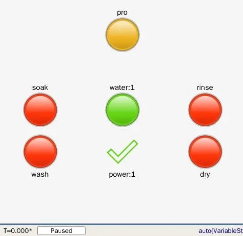
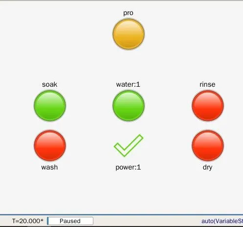
Fig.3.At Starting. Fig.4.At Soaking.
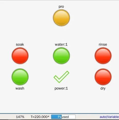
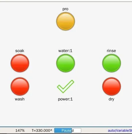
Fig.5.At Washing. Fig.6.At Rinseing.
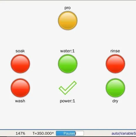
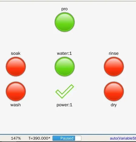
Fig.7.At drying. Fig.8.At Finishing.
Result:
From the above explaination here I am confirms that simulink model of washing machine using state flow logic has been done sucessfully.
-----------------------------------------------------------------------------------------------------------------------------------------------------------------------------------
Question No.2:
Make a Simulink chart for the “Gear shift” logic as per below conditions:
Speed Range(kmph) Gear
0 to 15 1
16 to 25 2
26 to 40 3
41 to 60 4
Above 61 5
Give speed input while the simulation is running & display the gear number.
Aim:
To built an simulink chart for gear shift logic as per above conditions.
Stateflow logic:
Speed Range(kmph) Gear
0 to 15 1
16 to 25 2
26 to 40 3
41 to 60 4
Above 61 5
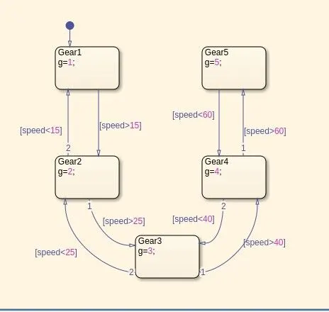
The state flow diagram consists of gear transition states. in each states we initialise an variable called g=0,1,2,3,4 & 5 with respect to states. Transition of state is done from one to another state is made possible by Speed conditions as given in the diagram.
Simulink model:
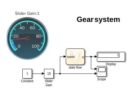
Blocks used:
- Circular gauge - This is an block from dashboard which gives the output of speed trnsition that we specified in its block parameter.
- constant - This block is used to multiply the value of 1 with value that varrying in slider gain.
- Slider gain - This block is used to give varrying input of speed to state flow logic during run time.
- Display - this block is used to show the current gear position.
- Scope - This block is used to give graphical respresentation of gear transition and speed with respect to time.
Procedure:
- Assign stop time as inf to run an simulation of infinite time period.
- After hit run button open slider gain block parameter window and give the speed input to state flow by changing slider switch in the same window.
- now we can see the speed range in gauge changes along with movement of slider switch. this tansition is viewed through display.
- Now hit the stop button and view the graph shows the all details about the speed and gear transition with respct too time.
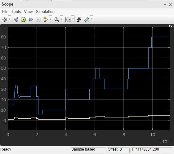
In scope blue and yellow line shows the speed transition and gear transition respectively.
Different States of gear Transition:
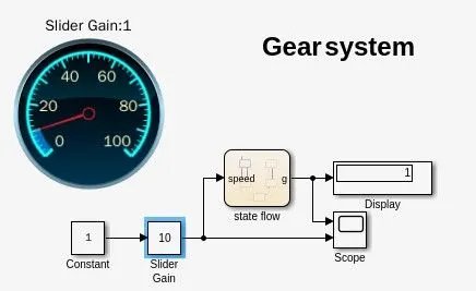
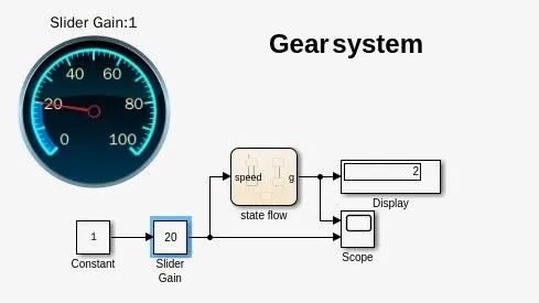
1st Gear at 10kmph 2nd Gear at 20kmph
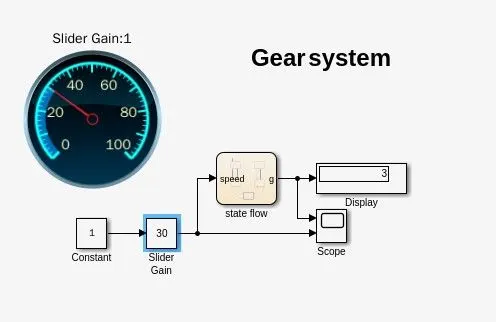
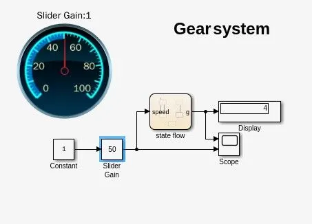
3rd Gear at 30kmph 4th Gear at 50kmph
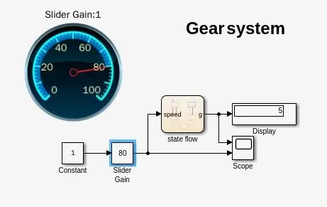
5th Gear at 80kmph
Result:
From the above explanation here i confirms that simulink model of gear system using state flow logic has been done sucessfully.