Week -2
QUESTION NO.1:
- Make a Simulink model of Doorbell using solenoid block with the following details:
In the above arrangement, when the switch is closed the electromagnet receives electrical power from the battery and pulls the metal arm to hit the bell producing sound.
Create a situation where the switch is closed for 2 seconds and then released. Observe the physical movement of the plunger.
AIM:
To simulate a model of door bell using pulse generater.
PROCEDURE:
Built a simulink model as shown below
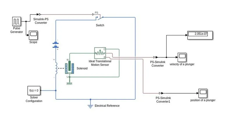
here we used a list of blocks such as
Pulse generater: this is an block which used to give pulsating signal that used to ring door bell for every 2sec.
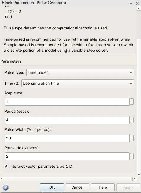
This pulse generater deals with 4 parameters such as amplitude, period, pulse width, phase delay. Amplitude is a value which represents a peak value of a pulse. period is a time at which an pulse has to occur.then pulse width is a value that represents the percentage level of peak value that shoud occur during a period of sec. then phase delay is the value that represents in what delay of time the pulse should occur.
Simulink-PS converter:
This block is used to convert the simulink signal into physical signal.
Switch:
This block is used to switch the solenoid depends upon the pulse that from pulse generater.
Battery:
This block is used to excite the solenoid by giving potential difference(V).
Solenoid:
This block is an elecromagnet that used to ring the bell using an plunger. By applying potential differnce to coil & it attracts plunger in transitional motion. transitional motion is outputed through the node R in solenoid block.
Ideal trnsitional motion sensor:
This block is used to measure transitional motion of a plunger by its position(p) and velocity(v).
Ps-Simulink converter:
This block is used to convert the physical signal that used in a physical system to simulink system.
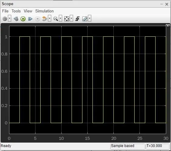
The above figure shows the pulse that inputed to the switch with an Amplitude=1;period=4sec;pulse width=50;pulse delay=2sec and stop time=30sec.
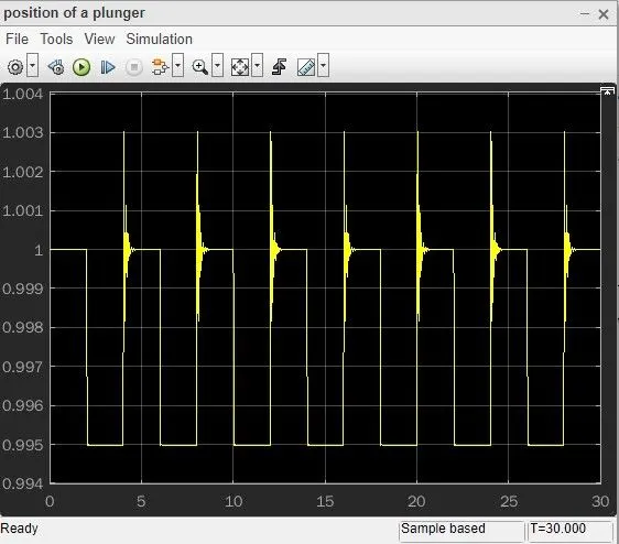
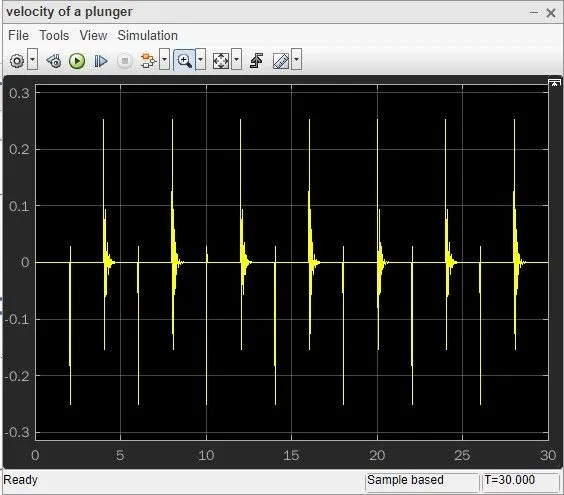
The above figure shows that the position of the plunger and velocity of a plunger after every 2 sec in about of 30sec.
Result:
the above experiment is simulated and ploted as a graphical representation.
QUESTION No.2:
Use a thermistor to sense the temperature of a heater & turn on or turn off the fan as per the below conditions:
Temperature source: 20 °C from 0 to 10 seconds, 27 °C from 10 to 30 seconds, 23 °C from 30 to 50 seconds
Fan conditions: ON if the temperature above 25 °C, OFF otherwise
AIM:
To simulate an model of thermister that have to control fan with respect to temperature.
procedure:
here the model of thermister fan.
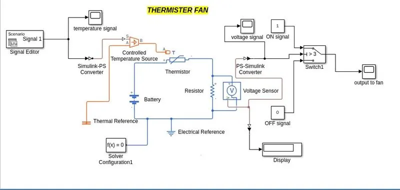
Signal Editor:
this block is used to give the parameterised signal to any of the physical block. in this experiment we using signal editor to give input to controlled temperature source.
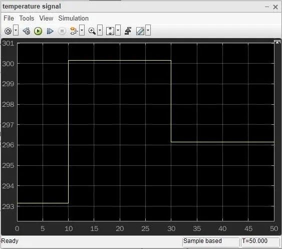
as they asked to give the signal for 20 °C from 0 to 10 seconds, 27 °C from 10 to 30 seconds, 23 °C from 30 to 50 seconds we disigned an signal showned in the above figure.
Thermister:
thermister is also called as thermal resistor. which has a negative temperature coefficient in which resistance decrease when temperature increases.
Voltage sensor:
voltage sensor is used to calculate the voltage drop across the resistor. this voltage signal iis used to switch the fan.
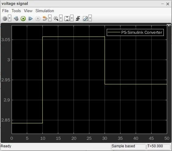
in the below figure voltage signal measured from resistor series with thermister is showned. were in 20degree voltage is 2.70v and in 27degree voltage is 3.25vand in 23degree voltage is 2.94v.
Switch:
this switch is used to regulate the output depends upon input signal.if input signal is greater than the threhold value of the switch then, the switch is get cosed and bypass the input signal with the next block connected through it. in this experiment according to the voltage that measured in the voltage sensor threshold value of the sitch is 3.
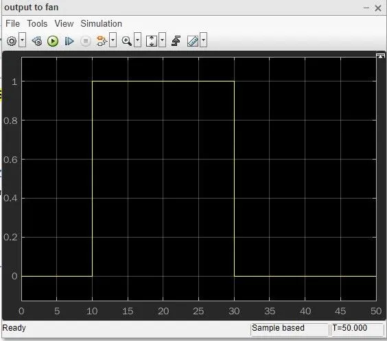
from the above figure we can conclude that from 0-10s voltage to the fan is 0 and in 10-30s were the temperature is 27degree so that the fan is in ON position as shown in the figure and in 30-50s fan is off condition.