Project
Question No.1:
Carry out a system-level simulation of an all-terrain vehicle.
Download the model from the given link:
https://www.mathworks.com/matlabcentral/fileexchange/70576-baja-all-terrain-vehicle-atv-model
Prepare a technical report explaining the model properties & comments on the results.
Aim:
To carry out a system-level simulation of an all terrain vehicle and prepare a technical report explaining the model properties of engine,cvt and vechicle body.
Simulik model:
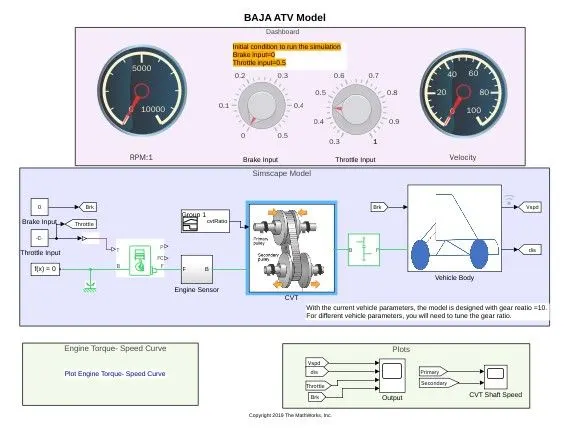
Fig.1.simulink model of Baja AVT.
The above mentioned simulink block consists of four blocks such as
- Dash board.
- Simscape model.
- Plots.
- Engine torque-speed curve.
1.Dash board:
This block consists of circular gauges to display RPM deliverd by engine and velocity possessed by vehicle. knobs for throttle of engine and brake of an vehicle. RPM gauge is linked with RPM scope under engine sensor subsystem and velocity gauge is linked with output velocity from vehicle body.
2.Simscape model:
This is an main block of the model where all the model are linked together.
- starting from the left there is two constant input for throttle and brake which is connected to the two knobs in dashboard respectively. then throttle is connected to engine and brake is connected to vehicle body by using Goto block.
- ENGINE block is used to generate an RPM by means of throttle as in real life. here we give throttle input from an respective constant and B is connected with mechanical rotational reference and F(crank shaft) is connected to engine sensor block.
- In Engine sensor block the rotational force which is also known as angular velocity(RPM) is measured using Ideal Rotational motion sensor. From this RPM only we connecting rpm gauge.from the fig.2 we get the pictorial connections.
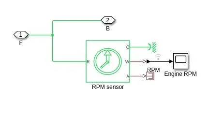
Fig.2.subsystem of engine sensor.
- Next block is an Continuously variable transmission block
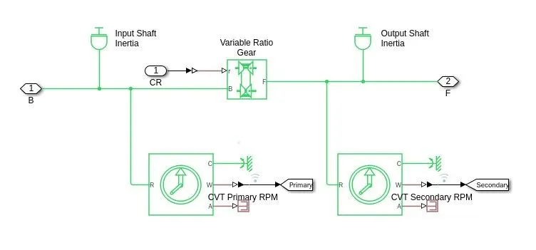
Fig.3.Continously variable block.
- In this block we using variable gear ratio which has a two gear positions as primarry and secondary shaft both are driven by a pulley as shown in a figure. When we change the correct cvt ratio input in signal builder it will change its primarry and secondary RPM ranges.
- r ,B and F represents cvt ratio, primary and secondary angular velocity respectively.
- Next the Output shaft is connected to an main gear box to axle of an vehicle which is an simple gear system.this is the main gear ratio which determines the velocity of this ATV.
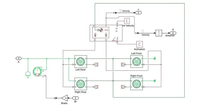
Fig.4.Vehicle body subsystem.
- After connecting simple gear box shaft with cvt output port(F) of gear box is conneccted with axle(A) of rear side left and right wheels. front side two wheels are connected to rotational free end which enables front wheels to rotate freely.
- H is the port which is connected to make an physical contact between vehicle body and wheel to move along with a thurst that generated by wheels.
- NF and NR are normal wheel forces created by front and rear wheels.
- Double shoe brake is connected to rear wheel axle.
- From the V port of vehicle body velocity is determined in output and an integretor block is used to integrate velocity with respect to time to fine the distance.
From the above explanations we get an clear idea of how the blocks are connected in a sequence to operate AVT.
PROCEDURE:
- To start the vehicle we should have to give theottle input above 0.5 and brake to be 0.
- After simulation get started respective gauges shows the velocity and RPM. Now we can varry the velocity using knobs and velocity will change according to the Engine RPM.
- variable gear ratio is given by signal builder.
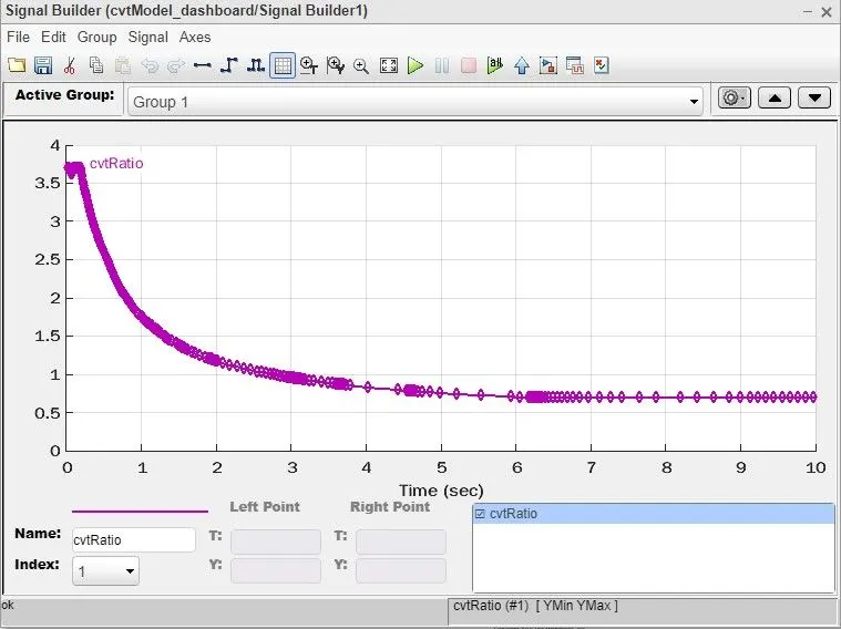
- From the above figure gear ratio is high at starting to give an high torque to make vehicle move and after some instances it is maintained in a constant ratio to give an constant torque with respect to throttle.
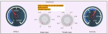
- from the above figure we came up with an information that for an gear ratio of 10 in simple gear highest velocity is 60kmph and 4000Rpm.
- now you can see the all parameters of an AVT in below shown windows.
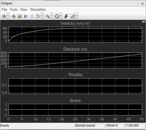
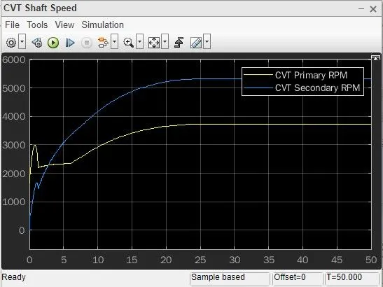
- fro the simulation time of 50s and gear ratio of 10 distance reached within 50s is approximately 800m
- If we change the gear ratio of simple gear we can change the output parameter. so, for that we change the gear ratio to 8. by decreasing gear ratio we can increase the RPM of output shaft. so, thats why we decreasing gear ratio to 8.
- the below fig shows parameters in gear ratio of 8.
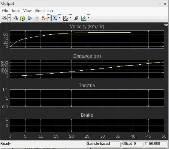
- from the above graph you can see distance reached is slightly greater than 800. so this proves by decreasing gear ratio we can increase the velocity and distances.
Result:
From the above graph you can see distance reached is slightly greater than 800. so this proves by decreasing gear ratio we can increase the velocity and distances.