Week - 4
QUESTION 1:
AIM:
- Implement control logic of a washing machine using stseflow as per given sequence.
Given the Data:
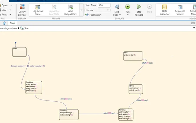
- If the power supply is avilable the system gets activated.
- If the water supply is not avilable, stop the process & indicated through led.
iii. Soaking time should be 20sec follwed by washing time of 10sec.
- then rinsing happens for ext 20sec & dryer runs for 50sec.
After all the process have completed turn on the finished LED
Theory:
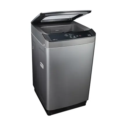
The concept of a washing machine is very simple - you soak your clothes in soapy suds and water to remove any dirt and stains before spinning to drain the water after a cycle. The main components of a washing machine are a drum, which is filled with water, but did you know that the washing machines actually have two drums, not one? Your central washing machine is made:
Internal drum. This is where you put the clothes when you are ready to wash. You will notice that the drum rotates slightly when you touch it and there are many holes drilled in the drum. These allow water to enter and wash clothes.
Rowers. These ridge sleeps on the edge of the drum and helps move your clothes around while you are washing.
Agitator. These are very common in high-speed machines and are a paddle in the middle that helps turn clothes into soapy water.
Outer drum. This is not visible when you look inside the washer, but there is another drum holding the water while the inner drum or pump is rotating. This part is completely waterproof to prevent your machine from leaking into the entire bathroom or kitchen!
Thermostat and heating element. These control the water temperature and heat the water to a specified temperature.
Pump. This drains the water from the drum after washing.
Coordinator. This controls the washing machine in every step from washing to washing and weaving.
Pipes and valves. These allow water to flow in and out of the washer.
Simulink model for washing machine:
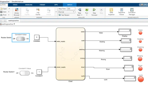
Block Used:
1.Chart
A finite Machine state machine is a repersenting of recative system
2.Display
The display is shown in the value of the input data.
3.Constant
The constant block generate a real or complex constant value signal.use this block to provied a constant signal input
4.Lamp
The lamp block display colur indicating the value of input signal . The lamp block use the block with the other dasbord bul;id on intarctive.
- Rocker Switch
The Rocker Switch block a button for operation that can be pressed on either end like a seesaw to connect or disconnect an electrical circuit. They are often used as ON/OFF switches on the main power supplies for electronic devices.
Logic Explanation
A rocker switch from the dashboard libray is used with a constant to supply the power and as water supply . A lamp is used to indicate the power status Sate and the water supply is checked for the soaking and the rinsing process . the timing for each stste is per the given inputs.
Flow chart of Washing Machine:
Symbols:
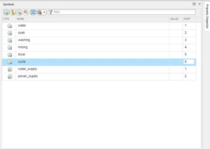
Water, Soak , Washing, Rinsing , Dryer, Cycle is Output of the Chart.
Water_Supply & Power _ supply as Inputs of the chart.
Simulation Time:
I used the 430Sec whole cycle are sufficient time.
Condition1:
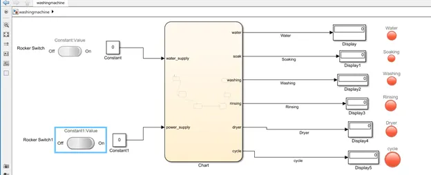
Water supply & Power Supply is Off .
Condition2:
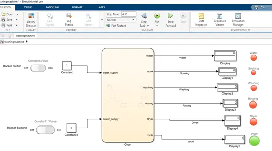
Water supply & Power Supply is ON.
Values 1 means Ther is Input
Values 2 means There is No input
When Lamp show is Red task completed The Lamp show is Green Task in Progress.
CONCLUSION:
The simulation Of the washing Machine using state flow is work good .and the result is staisfactory.
………………………………………………………………………………………………………………………………………
Question:-2
AIM:
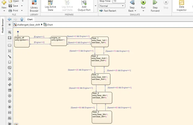
‘To make a simulink chart for the “Gear Shift” logic as per below condition.
Given the Data:
Speed Range (kmph) Gear
0 to 15 1
16 to 25 2
26 to 40 3
41 to 60 4
Above 61 5
Theory:
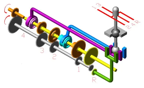
The most basic case of a gear train is the transmission and power transmission between two parallel shafts. This is a two-dimensional case that allows for visibility on the plane. If the rotation transmission is to occur at a constant rate, which means that in the event of constant or parallel RPM insertion, a constant output RPM is required, then it is necessary to satisfy the following form of rotation rule: Gear system: Gear system is a precision transmission tool from one point to another. The gear is a wheel with teeth around its edge. The teeth act as parts of a machine and transmit rotary movements to the wheel by connecting the teeth in a rotating gear.
Simulink model for Gear shift:
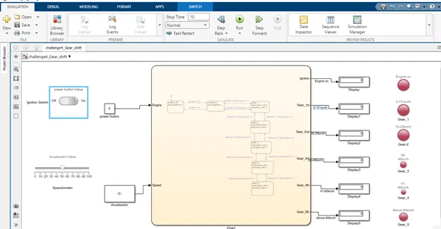
Block Used:
1.Chart
A finite Machine state machine is a repersenting of recative system
2.Display
The display is shown in the value of the input data.
3.Constant
The constant block generate a real or complex constant value signal.use this block to provied a constant signal input
4.Lamp
The lamp block display colur indicating the value of input signal . The lamp block use the block with the other dasbord bul;id on intarctive.
- Ignation Switch
An ignition switch, starter switch or start switch is a switch in the control system of a vechile that activates the main electrical systems for the vehicle,
6.Speedometer
Speedometer as the input of speed for acclerate value.
Flow chart of Gear Shift:
Symbols:
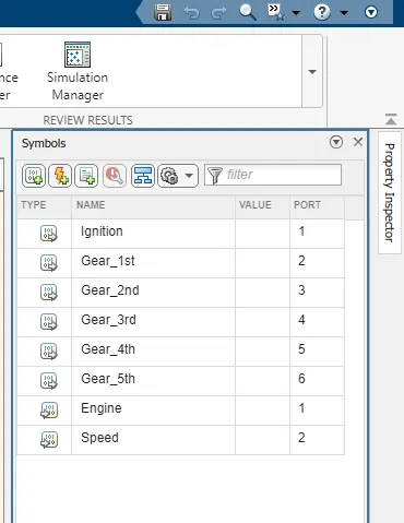
Speed as an Input for the chart.
Gear as an Output.
Simulation Time:
I used the 10Sec our simulation should run untill We stop it.
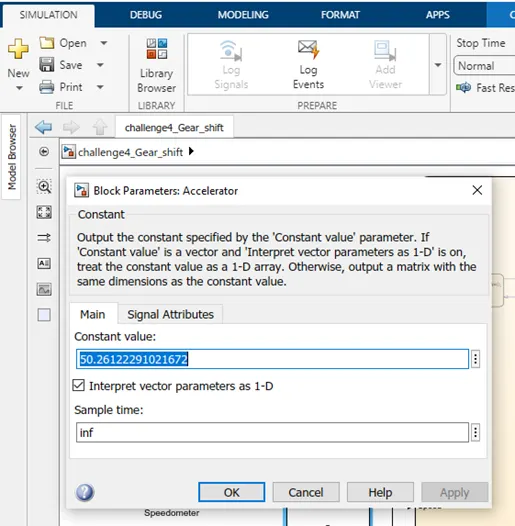
INPUT:
I used Acclerator to provied input of the chart.
OUTPUT:
The Output Produced is recorded When it’s Display the each gear.
Gear:-1
Speed range : 0 to 15 kmph
Input Speed : 12 kmph
Color : Yellow
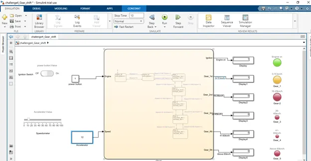
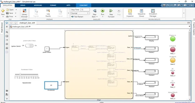
Gear:-2
Speed range : 16 to 25 kmph
Input Speed : 22 kmph
Color : Yellow
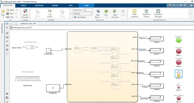
Gear:-3
Speed range : 26 to 40 kmph
Input Speed : 36 kmph
Color : Yellow
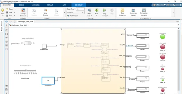
Gear:-4
Speed range : 41 to 60 kmph
Input Speed : 55 kmph
Color : Green
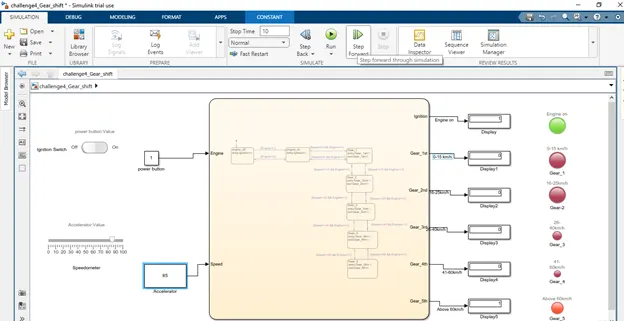
Gear:-5
Speed range : Above 61
Input Speed : 85 kmph
Color : Red
Conclusion:
And all the condition simulated through staeflow chart sucessfully.
*********.......*** **** THE END *********.............*******