Week - 4
1.AIM:To implement control logic of a “washing machine” using Stateflow as per given sequence by configuring the below condition in an stateflow model.
State flow model and description: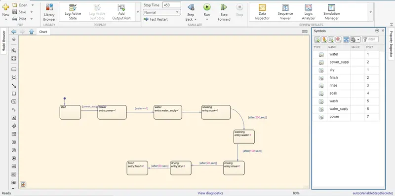
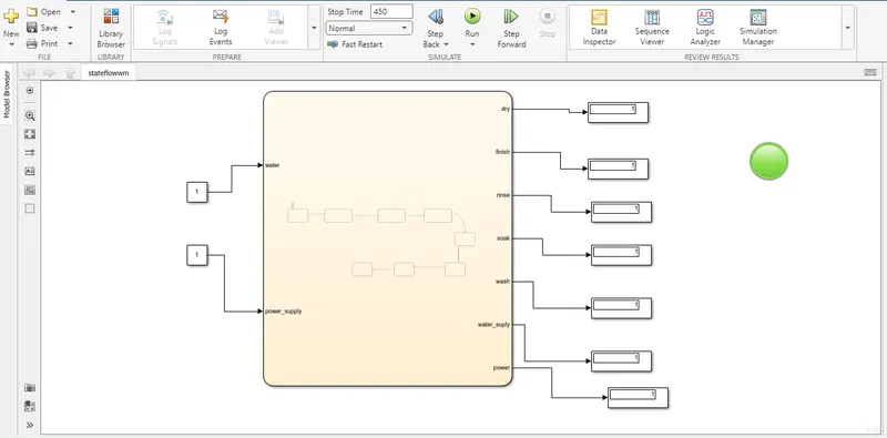
In the state flow model we have used the different states for starting, power supply,water supply,Soaking,Washing,rinsing and for an stop.As per the given condition i.e,If the power supply is available, the system gets activated and If the Water supply is not available, stop the process & indicate through LED in the output side and Soaking time should be 200s followed by Washing time of 100s and then finally rinsing happens for next 20s & dryer runs for 50s.
With the chart library browser we are going to build an state flow model with the help of states and the respective conditions as per that condition 1 is assigned for an ON condition and 0 is for an OFF condition, the symbols pane is used for assigning an input and ouput for the state flow model.and for the input of the model the constatnt blocks are used and for the output of the model the display blocks along with that lamps are used to see the LED lights as per the confirged condition
REPORT: As per the condition the stateflow model has been configured and we have assigned one for ON mode and 0 for an OFF mode for both the input side i.e,for the water and the power supply.In first report it can be clearly observed that 1 is given for water and 0 is for power if there is no power then there will be no activities occuring in an washing machine so in the ouput display part it has been projecting an output as an 0.And the lamp is connected to the finish end and it is configured with the red color for 0 so we can observe in an red color,were as in the second case we can see there is power supply which is given as an 1 ,as per our condition if we give power supply all the activities in the washing machine should work as per the condition and we can see one in the output i.e,in the display browser and green color & 0 for red in the LED display 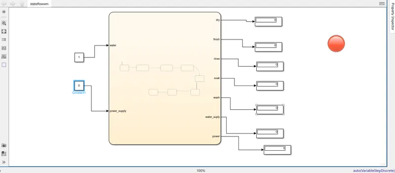
2.AIM:Make a Simulink chart for the “Gear shift” logic as per below conditions
State flow model and description: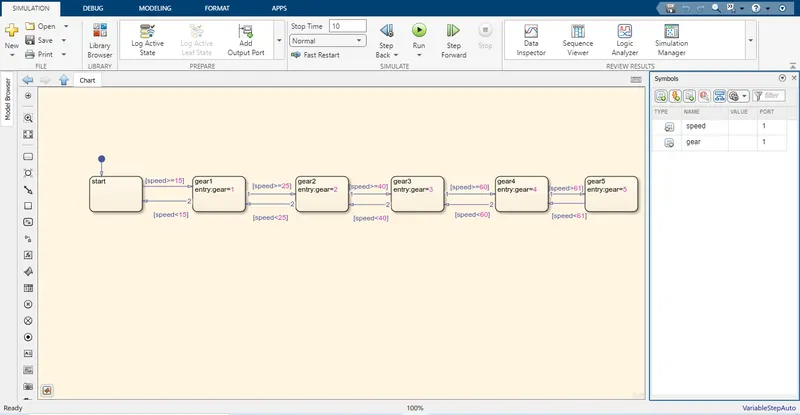
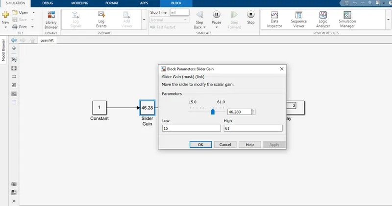
As per the given condition the state flow model has been configured i.e,Speed Range(kmph) as 0 to 15,16 to 25,26 to 40,41 to 60,Above 61 for an gear condition of 1,2,3,4,5 with the help of states and with the help of an symbols pane the input and output for an model is given in this condition the speed is given as an input and for the output gear is connected.And the slider gain block is used for giving input to the chart by the slider gain we are able to change the speed and see the gear number in the running condition.
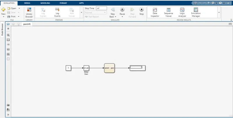 To the chart model the input is given to the slider gain as we need to see the simulation is running & display the gear number in the ouput side we have given an display as the output.For the slider gain the constant 1 should be added since one input has be connected in the input side of an slider gain.
Report:We should give as stop time as an infinite because in the question it has been mentioned that to give speed input while the simulation is running & to display the gear number in the output side.from the below attached picture you can obserrve that when we are going to change the input with the help of an slider gain in an running condition the change in the ouput gear number can be observed.From the above illustartion the condition holds good for the configured model.