Week - 4
Week 4- Challenge
- Implement control logic of a “washing machine” using Stateflow as per given sequence:
- If the power supply is available, the system gets activated
- If the Water supply is not available, stop the process & indicate through LED
- Soaking time should be 200s followed by Washing time of 100s.
- Then rinsing happens for next 20s & dryer runs for 50s
- After all the processes have completed turn on the finished LED
- Make a Simulink chart for the “Gear shift” logic as per below conditions:
Speed Range(kmph) Gear
0 to 15 1
16 to 25 2
26 to 40 3
41 to 60 4
Above 61 5
Give speed input while the simulation is running & display the gear number.
NOTE: If you are using MATLAB R2021a above versions, kindly convert you to lower or equal to R2021a version and attach it in the submission.
Conversion: Save > Pervious Version > Choose R2021A or lower version.
Grading Policy:
Upload the supporting results as images or by any other means
Write a detailed report
Report attached as an image will lead to zero marks
plagiarism is not tolerated
upload Simulink files if needed through the google drive, any external links will not be accepted
Question 1
Answer:
Solution:
- Implement control logic of a “washing machine” using Stateflow as per given sequence:
- If the power supply is available, the system gets activated
- If the Water supply is not available, stop the process & indicate through LED
- Soaking time should be 200s followed by Washing time of 100s.
- Then rinsing happens for next 20s & dryer runs for 50s
- After all the processes have completed turn on the finished LED
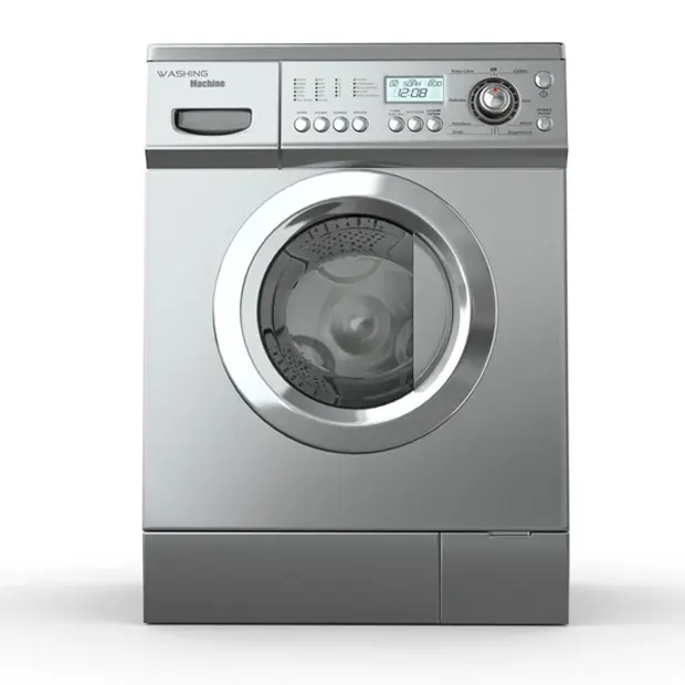
Washing Machine Components and Functions:
An Inner Drum
This is the chamber in which the dirty clothes are put. On noticing properly, one may see many holes in this, and these holes are made so that the water can enter the drum and the cleaning process also takes place here.
Paddles
paddles are the ridges present on the drum’s edges and help move the clothes while it is present inside the drum.
The Outer Drum
This is the drum inside which the inner drum is present. This is the water-tight area of the machine that prevents the leakage of water from the machine.
Agitator
This is not a default part of the washing machine. Agitators are present only in the premium models and help turn around the machine’s clothes and make cleaning more effective.
Thermostat And Heating Element
This part of the machine checks the water temperature and heats it according to the need.
Pump
It helps remove the water from the drum after the cleaning process is over.
Pipes And Valves
These elements are often overlooked but are the machine’s most fundamental elements. These pipes and valves help maintain the to and fro movement of the water from the drum, allowing the washing to occur.
Programmer
This element can also be termed as the CPU of the washing machine. It controls all the aspects of the entire process, right from starting up to drying.
When the washing machine was first invented, it was thought of as a luxury, but nowadays, it is an essential part of a household. The development of washing machines has been enormous and more and more advanced features are coming this day, thanks to the rapidly advancing technology.
Fully automatic washing machines are the latest variants to come, making washing an effortless and less tiresome task. However modern the appliances become; their principle of working remains the same. These principles based on physics laws are the backbone of all the machines involving the washing machine.
Hope you learned about how a washing machine works and principle behind its working mechanism.
Stages of the washing machine:
Let us now undergo the stages of a washing machine which in turn helps you to understand better and pick the option depending on the basis of your need successfully.
- Prewash
- Washing
- Rinsing
- Spinning
Modelling of a washing machine in Simulink:
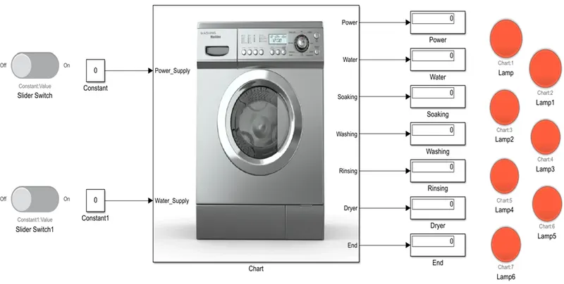
For modelling a washing machine, we have to create a subsystem of logical blocks for different stages
- Toggle switch
- Constant block
- State flow chart
- Lamps
- Display
Simulink Model For washing machine
Sateflow Logic for washing machine
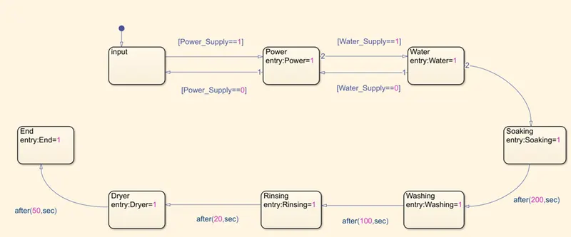
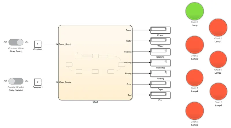
When power supply ON, Water supply OFF output Power Lamp only Glow.
When power and water supply ON, stop time less than 212 sec then Power, water and soaking Lamp will glow.
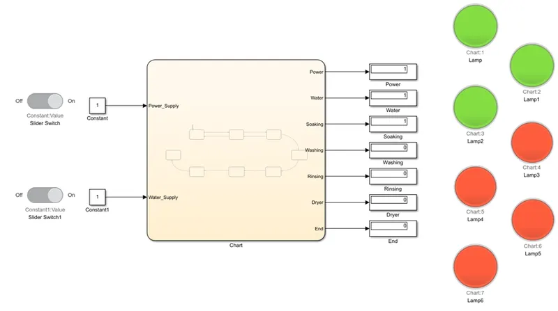
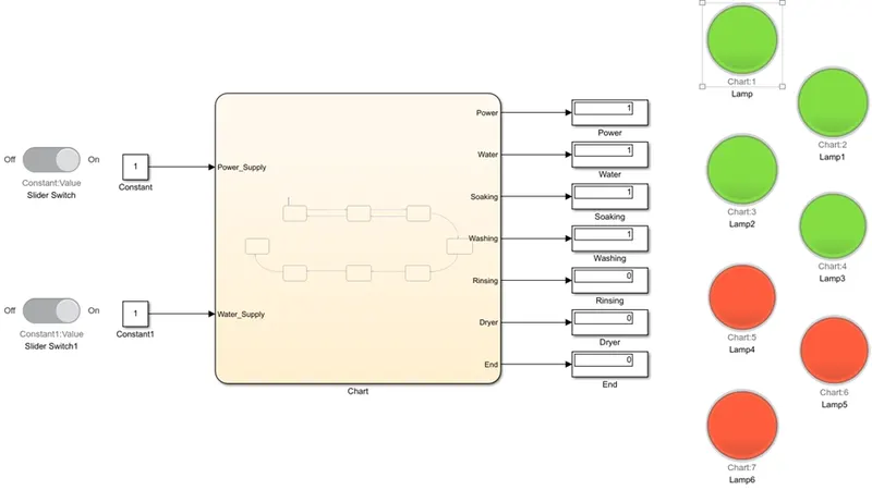
When Power and water supply ON, stop time is 213-322 sec then washing Lamp also Glow.
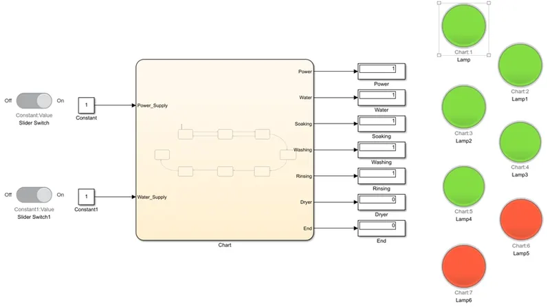
When the power and water supply ON, stop time is 223-344 sec then rinsing also ON.
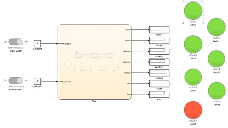
When the power and water supply ON, stop time is 345-416 sec then dryer also ON.
When the power and water supply ON, stop time is more than 417 sec then machine is stopped, and End Lamp also Glow.
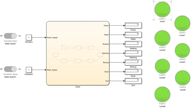
Power and Water supply ON (constant block value Is 1) then
- 1-212 sec lamp 1,2,3 (Power, Water and soaking is on)
- 213-322 sec lamp 4 (washing ON)
- 323-344 sec lamp 5 (rinsing ON)
- 345-416 sec lamp 6 (dryer ON)
- After 417 sec lamp 7 (End LED ON)
Question 2
Answer:
Explanation:
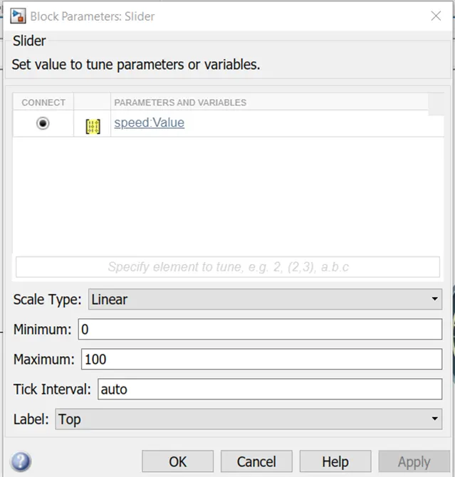
- The stateflow chart is having two inputs which are speed and engine. The speed input is connected to a constant block named ‘speed’. Constant block is connected with the slider switch named ‘speed:value’.
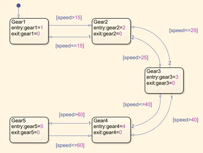
- All the state connected one by one with condition speed value come above or blow the logic output value is shown in display. i.e.- when run the model speed is zero then as per logic 0-15 value is showing gear 1.
- If the speed is 16 to 24 the showing gear is 2 actives. If below 25 or greater than 16 then also showing gear 2. but is the value is more then 25 then passes condition to the next block and next block check the logic condition >=25 then passes to the next block logic and showing gear is 3 enable and rpm. But when and <=25 then value come back to previous block and showing again gear 2 Is active.
- In the final block check the condition is if the speed >= 100 then showing gear 5 or we can use a output is ‘overspeed’. If less than 100 gear 5 is showing green.
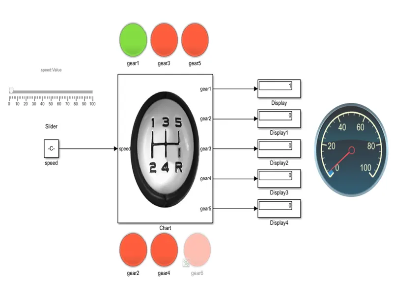
When Speed is 0 to 15 showing gear is 1
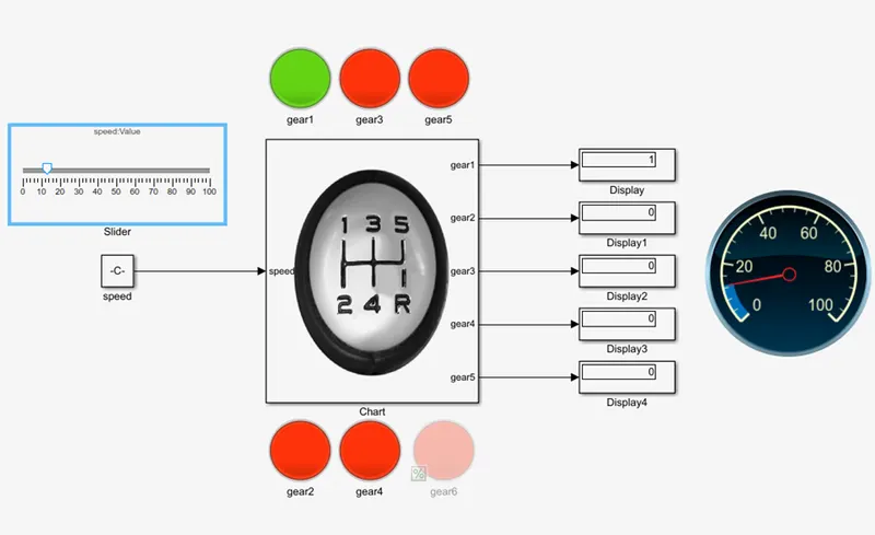
When Speed is 16 to 25 showing gear is 2
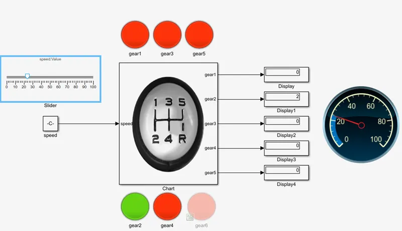
When Speed is 26 to 40 showing gear is 3
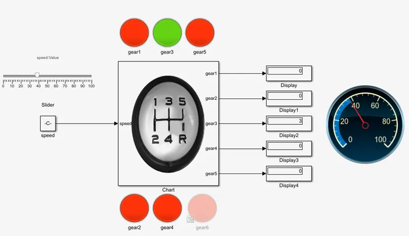
When Speed is 41 to 60 showing gear is 4
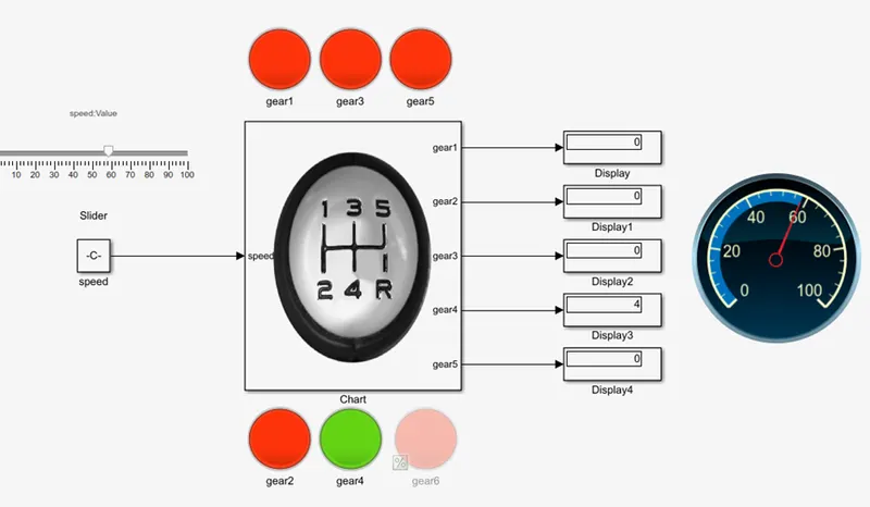
When Speed is above 61 showing gear is 5
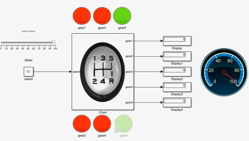
Logic chart for gear switch.
Speedometer gauge connect with speed output constant block.
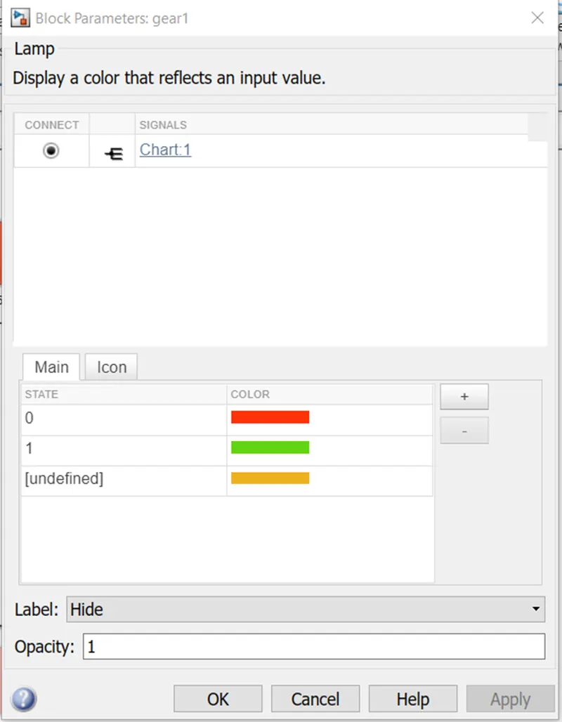
Lamp connect with chart 1. Set 1 as Green, Red as OFF.
Run simulation successfully.