Week -2
Week 2 – Challenge – Manual Grade
1. Make a Simulink model of Doorbell using solenoid block with the following details:
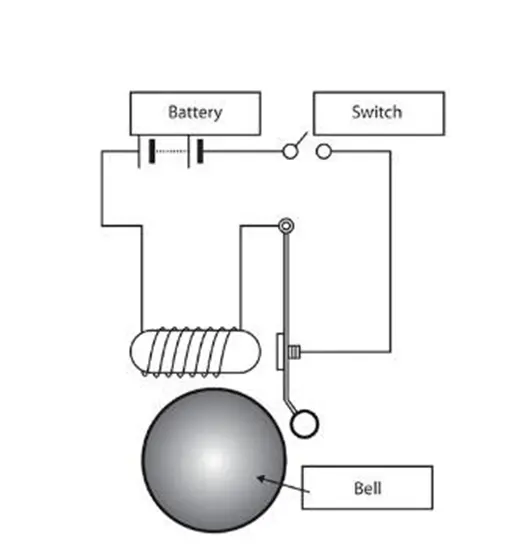
In the above arrangement, when the switch is closed the electromagnet receives electrical power from the battery and pulls the metal arm to hit the bell producing sound.
Create a situation where the switch is closed for 2 seconds and then released. Observe the physical movement of the plunger.
- Use a thermistor to sense the temperature of a heater & turn on or turn off the fan as per the below conditions:
Temperature source: 20 °C from 0 to 10 seconds, 27 °C from 10 to 30 seconds, 23 °C from 30 to 50 seconds
Fan conditions: ON if the temperature above 25 °C, OFF otherwise
NOTE: If you are using Matlab R2021a above versions, kindly convert you to lower or equal to R2021a version and attach it in the submission.
Conversion: Save > Pervoius Version > Choose R2021A or lower version.
Grading Policy :
- Upload the supporting results as images or by any other means
- Write a detailed report
- Report attached as an image will lead to zero marks
- plagiarism is not tolerated
- upload Simulink files if needed through the google drive, any external links will not be accepted
AIM:
- Construct the Simulink Model for Doorbell using Solenoid.
- Construct the Simulink Model for Sensing the temperature of a heater and ON or Turn OFF the Fan using Thermistor.
Topic 1:
Before making the Solenoid Project we have to Know the basics of Solenoid coil and how to work as a bell.
Solenoid:
A Solenoid is a type of electromagnet. The purpose of the coil is generating a controlled Magnetic field through a coil. This coil is tightly packed into helix. We can call solenoid is a Helical coil
Solenoid Block:
The solenoid block in the Simulink is used for creating a solenoid diagram of a model.
In this construction of a solenoid model system acts as a working principle of a doorbell.
Doorbell and Switching Conditions:
- When the switch is close received electrical power to the coil and coil pull the metal plunger to hit the bell with vibration then bell pricing a sound like bell.
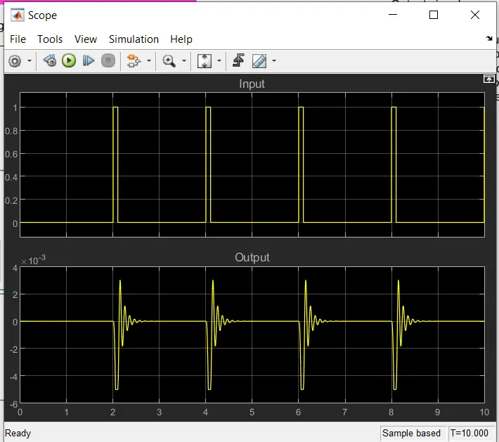
- Create a Simulink where the switch is closed for 2 sec and then release for doorbell.
- Observe the physical movement of the plunger for the make plot whether the switch is on or off.
Construct the Simulink Model for Doorbell using solenoid:
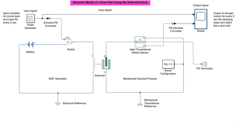
- Solenoid coil is in the Simulink library from – Smiscape-Electrical- Electromechanical- mechatronic actuators.
- Solenoid here work like a doorbell. Where the electromagnet received electrical power from battery and pull the metal arm to hit the bell. Then bel producing sound. Metal arm is a plunger in the solenoid block.
- In the solenoid block consists of an electrical and a mechanical system.
- In the electrical system we generate source voltage so that it produces EMF to the coil to magnetize.
- In the mechanical system the plunger is attracted when the coil generates EMF.
- For the ON OFF we give a switch block in the electrical system.
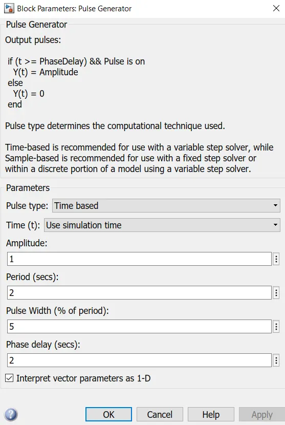
- We take switching condition from the pulse generator block. Where we cerate the condition for the switch to Run every 2 second the switch is open and close.
- In the mechanical system output is taken from the scope plot to display at which time the lunger damping is moving for every 2 sec.
Simulink Block Diagram:
Input and Output Plot:
Pulse Generator parameters:
Topic 2:
Construct a Simulink Model for the Sensing temperature of heat and turn ON-OFF the fan using the Thermistor.
Condition for temp source and fan condition:
- Temp source
- 20 deg c from 0 to 10 sec of a time period.
- 27 deg c from 10 to 30 sec of a time period.
- 23 deg c from 30 to 50 sec of a time period.
- Fan condition
- When the temp source is below 25 deg c fan is in OFF condition.
- When the temp source is above 25 deg c fan is in ON condition.
Blocks used in the model:
- Thermistor:
Thermistor is a resistance thermometer or a resistor whose resistance is dependent on the temp. the term is a combination of “thermal” and “resistor”. It is made of metallic oxides, pressed into a bead, disk or cylindrical shape and then encapsulated with an impermeable material such as epoxy or glass.
- Temp source:
A temp source is a constant source of thermal energy.
- DC motor:
A dc motor of a class of rotary electrical motor that convertes direct current electrical energy into mechanical energy. It can act as aFAN is our simulation.
- Ideal rotational motion sensor:
The ideal rotational motion sensor block represents an ideal mechanical rotation motion sensor.
- Controlled voltage source:
The controlled voltage source block is representing an ideal voltage that is powerful enough to maintain the specified voltage at its output regardless of the current flowing through the source where v=vs.
- Voltage sensor:
The voltage sensor block represents an ideal voltage sensor that is a device that converts voltage measure between two points of an electrical circuit into a physical signal proportional to the voltage.
Construct the Simulink model for sensing the temp of a heat and turn ON or OFF fan using thermistor:
In this simulation we use three systems –
thermal system
electrical system
mechanical system.
By these three systems blocks we create a simulation model for sensing the temp of heat and turn ON and OFF the fan using a thermistor.
Steps:
- Let’s create the temperature source condition using the signal builder block. Where give all the time range of 0 to 50 sec as per the question total time is 0-10,10-30,30-50 sec.
- For creating signals in signal builder need to assign signals. First open a signal builder block and click Axes on the top menu bar.
- Select time range min and max 0-50 sec.
- Assign signal by click Signal behind axes menu. Click New- custom- Time value (x) and y values (temp in kelvin).
- y values under [] like- [293.15 293.15 300.15 300.15 296.15 296.15]
- Signal value in kelvin . convert deg c to kelvin by formula (i.e. 20+273.15=15)
- Time value (x) also put under []. i.e. [0 10 10 30 30 50]
- 20 deg c (293.15 k) from 0 to 10 sec of a time
- 27 deg c (300.15 k) from 30 to 50 sec of a time
- 23 deg c (296.15 k) from 30 to 50 sec of a time.
- After assign X Y showing signal in chat.
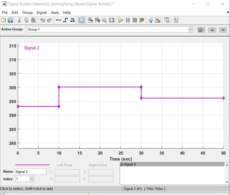
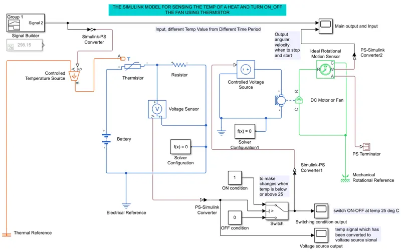
- After that signal builder is connected to a controlled temp source block. In between control builder and control temp block connect a Simulink-PS for converting Simulink signal into physical signal.
- Now electrical system the value of the thermistor is taken. Thermistor physical port A connected with temp source block B. this is NTC thermistor. when the temp more then 25 deg c thermistor resistance value is become reduced and voltage sensor sense the voltage and send to switch. Voltage sensor V port and switch U2 port connection with PS-Simulink converter.
- Switch port U2 is enable when the voltage sensor out the signal 1. As per switch logic switch output port is connected to off condition. when U2 > 1 then pass the on condition signal to dc motor control voltage block. And turn on the FAN or DC Motor.
- DC Motor is connected to a ideal rotational motion sensor R port. When the detect rotation form DC motor signal out from the W port. Port C of the Motor and Moton sensor is connected to a mechanical ref block. The ideal rotational motion sensor output connected with a PS-Simulink block and then connect with a scope for showing output.
- condition that when temp source is below 25 deg c FAN or DC Motor is in OFF condition.
- When the temp source is above 25 deg c FAN or DC Motor is in ON condition.
- For every system we need to put a reference point which is thermal ref, electrical ref, and mechanical rotary ref blocks.
- Connect solver configuration block to a mechanical electrical system before running the model.
- I connect 3 scopes for measure value of :
- Voltage source output signal (temp signal converted into voltage source signal)
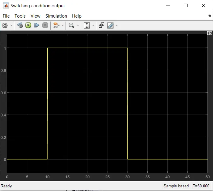
- Switching condition output(switch ON-OFF at temp 25 deg c)
- Main output and input scop
Simulation Block Diagram:
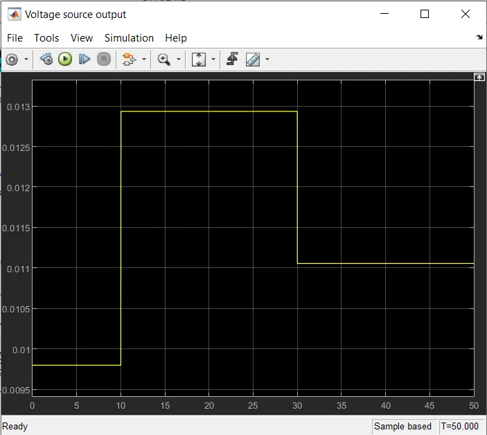
Voltage source output:
Voltage at temp source is
9.799 mV from 0 to 10 sec of time.
12.935 mV from 10 to 30 sec of a time.
11.055 mV from 30 to 50 sec of time.
Switching condition plot:
For temperature
- When the temp source is below 25 deg c fan is in OFF condition.
- When the temp source is above 25 deg c fan is in ON condition.
- Temp is above 25 when temp is 10-30 sec That time temp is >25 deg c. then again false from 30-50 sec. when temp is going below 25 deg c switch is false condition.
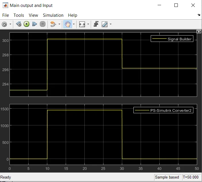
Main input and output results:
When run the simulation for 50 sec.
Output signal of motion sensor or dc motor output is 0 rad/ms from the 0 -10 sec of time
From the time 10-30 sec output is 1.454 rad/ms and after 30-50 sec of time the angular velocity is reduced to zero.