Week - 4
1) To implement control logic of a washing machine using Stateflow in Simulink.
Conditions:
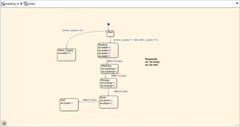
i) If the power supply is available, the system activates.
ii) If water supply is not available,stop the process and indicate through LED.
iii) Soakiing time should be 200s followed by washing time of 100s.
iv) Followed by rinsing for next 20s and in the last the dryer runs for 50s.
After all the steps completed turn on the finished LED light.
Pictorial representation of block diagram:
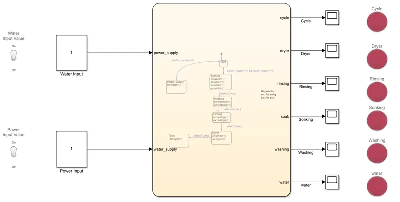
Chart Diagram:
Parameters:
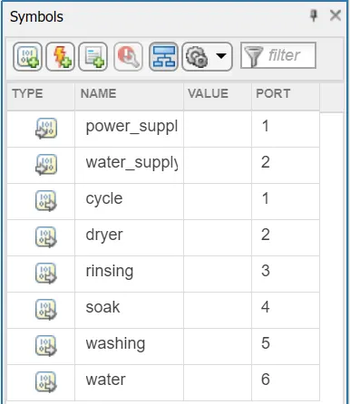
- water_supply and power_supply are input to the chart on the other hand water, soaking, washing, rinsing, dryer and cycle are outputs of the chart.
->Simulation time=500s
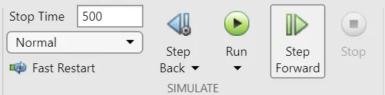
Output:
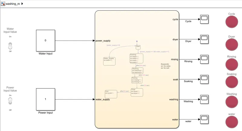
Condition I) When water supply is OFF
Result: In the diagram below we can see that process is terminated due to no water supply shown by LED in red.
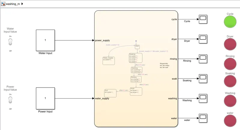
Condition II) When water supply is ON
Result: In the diagram below we can observe that when we supply the water the process is executed and cycle (representing the process completion block) is indicating green signal.
Conclusion:
The simulation for washing machine using statefow was executed and results were satisfactory.
2) To make a Simulink chart for 'gear shift logic'.
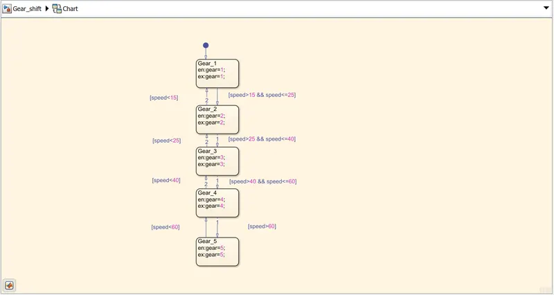
Parameters:
| Speed range (kmph) | Gear |
| 0-15 | 1 |
| 16-25 | 2 |
| 26-40 | 3 |
| 41-60 | 4 |
| 61 and above | 5 |
Block diagram of the model:
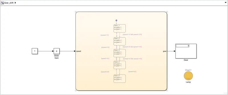
Chart:
Parameters:
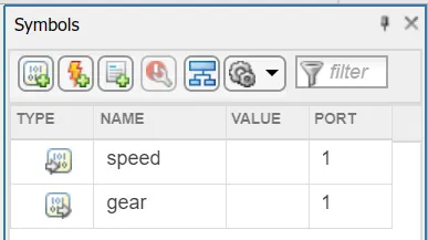
Speed as input and Gear as output.
Input:
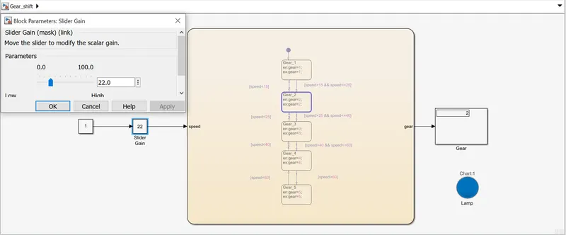
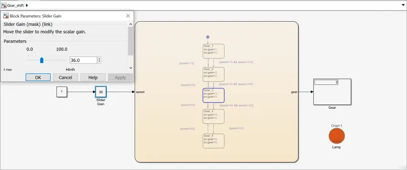
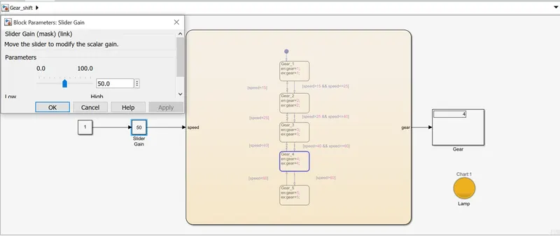
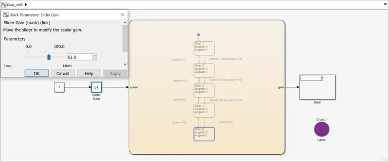
We use slider gain to input speed values to the chart.
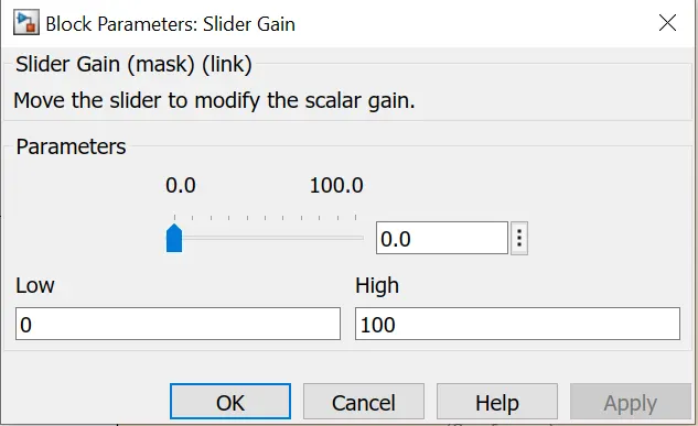
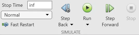
Therefore, run time is set at infinite.
Output:
Gear 1:
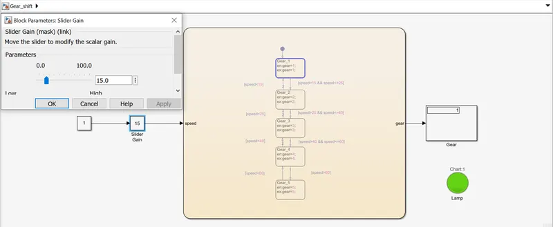
Gear 2:
Gear 3:
Gear 4:
Gear 5:
Conclusion:
Stateflow was created using Simulink for gear shift and results were satisfactory.