Week - 4
Q1)
Implement control logic of a “washing machine” using Stateflow as per given sequence:
Representation of the diagram:
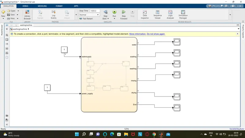
Parameters:
The power supply value =1 represents power on.
The water supply value =1 represents watersupply on.
Chart: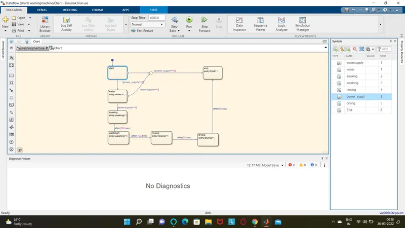
The following chart has 2 parameters
INput and output parameters.
Input parameters are watersupply and power supply.
Out put parameters are soaking,washing,rinsing,dryer,cycles.
When the power supply and the water supply that is the value is 1. the further process of the washing machine takes place.
Q2)
Make a Simulink chart for the “Gear shift” logic as per below conditions:
Speed Range(kmph) Gear
0 to 15 1
16 to 25 2
26 to 40 3
41 to 60 4
Above 61 5
Give speed input while the simulation is running & display the gear number.
Model.
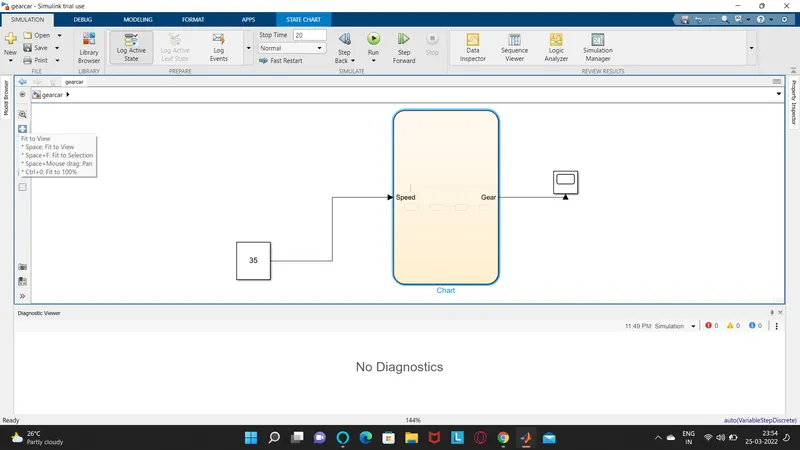
In the model given above the speed taken is 35.
Chart:
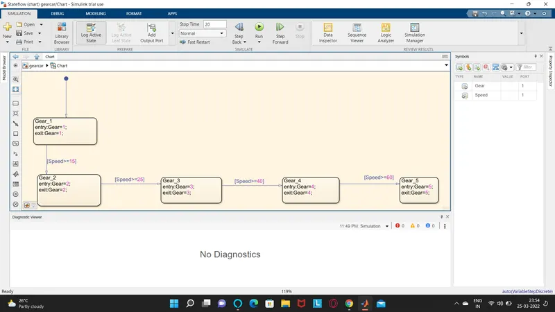
The chart is provided according to the given condition.
In the chart the speed is taken as the input and gear as the output.
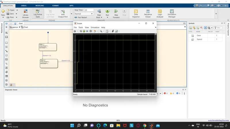
For the given speed thee third gear is selected.
The details are missing due to unavaliabllity of the one on one session slots.