Week - 4
Part 1:
Aim:
Implement control logic of a “washing machine” using Stateflow as per the given sequence.
Objective:
- If the power supply is available, the system gets activated
- If the Water supply is not available, stop the process & indicate through LED
- Soaking time should be 200s followed by Washing time of 100s.
- Then rinsing happens for the next 20s & dryer runs for 50s
Input Conditions:
The different states of washing machines,
- Soaking-200sec (0-200sec)
- Washing- 100sec(200-300sec)
- Rinsing-20sec(300-320sec)
- Drying/Spinning- 50sec (320-370sec)
- Completed/ Stop the machine.
Blocks used in the Simulink model:
- Stateflow Chart:- For showing control logic in the washing machine model.
- Display Block:- This block is used for displaying the output result of a given logic.
- Constant Block:- This block is used to give any constant/fixed value as input.
- Toggle switch:- The Toggle Switch block toggles the value of the connected block parameter between two values during simulation.
- Lamp:- Display a color that reflects an input value.
Stateflow Logic Chart:
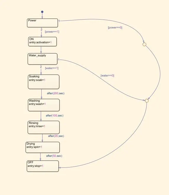
Explanation:
- Initially, we have created a power state and after going through the power state, we have applied one condition [power==1] means if power is there, it goes to the second state (ON state).
- If power is not detected, means it goes through condition [power==0], and it further goes to the OFF state condition.
- As soon as power is detected, the second state (ON state) got activated and it goes to the third state Le Water supply.
- After going through the third state (Water_supply), it goes through water conditions. That means, if [water==1] condition satisfied, then it goes to soaking state for soaking operation for 200 sec. If [water==0] condition got satisfied, then it goes to OFF mode where the machine stopped and the stop lamp got activated.
- When the soaking operation is done for 200 sec, it got shifted to the washing state, and washing is done for 100 sec. After washing state, it goes to rinsing state for 20 sec where rinsing operation works.
- After the rinsing state got completed, it goes to the drying/spinning state for 50 sec where the spinning/drying process works for drying the clothes.
- After the drying/spinning state got completed, the machine goes to the OFF state confirming it has followed all the washing steps and washing got completed for clothes, and the machine got stopped.
Simulink before running the model:
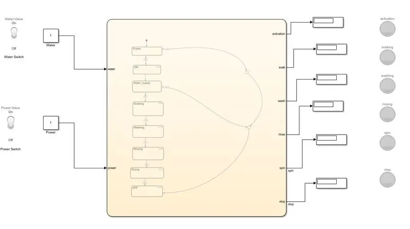
Steps:
1. Power and Water supply given to the Washing machine are dependent upon the toggle switch conditions which is on or off and it is defined by the constant value 0 or 1.
2. The signal is then given to above state flow logic. If the value displayed is 1 for the power and water supply block then water and power supply will be given to Washing machine.
3. If the value is 0 and 1 for water and power supply respectively, then the machine will start however, the machine won't execute any washing process as one of the switches are off. It means that machine detects that water supply is not available and goes to OFF state to turn OFF the machine.
4. Also, if the value is 1 and 0 for water and power supplt respectively, then the machine will not even start because of no power input was provided.
5. When both power and water supply are at I then the soaking process starts and run for 200 sec, after this washing process will start and it lasts for further 100 sec.
6. Thereafter, the rinsing process starts and lasts for 20 sec. Thereafter, the drying process is started for 50 sec which the water supply is cut off and drying of clothes will execute.
7. After completing all the washing tasks, the washing machine goes to OFF state indicating that all tasks completed and turns off the machine and stop lamp and got activated.
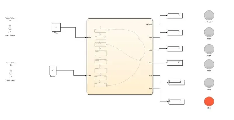
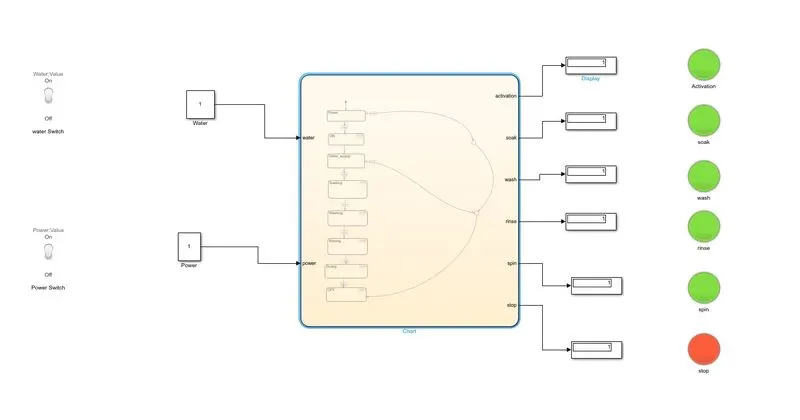
8. For all the different process or states of the machine, the lamp indicates green for working and red for not working. However, for stop process (OFF state) we have given red color as true condition. So, that when machine goes to OFF state. This all gives a better idea to user, now which process is going on in the Washing machine.
Google Drive Link: https://drive.google.com/file/d/1nsXRQdGNcfMddWQd75nOwIWhjEC08_p8/view?usp=sharing
Differrent condition on which the above washing machine model worked:
1)Water supply OFF & Power supply OFF
2) Water supply ON & Power supply ON
3) Water supply OFF & Power supply ON
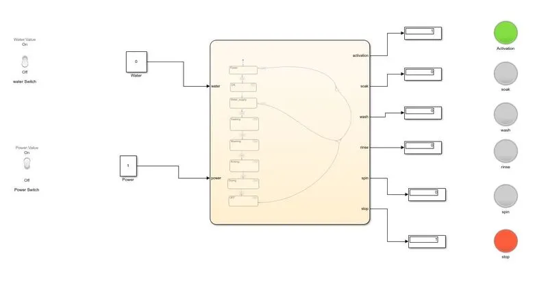
4) Water supply ON & Power supply OFF
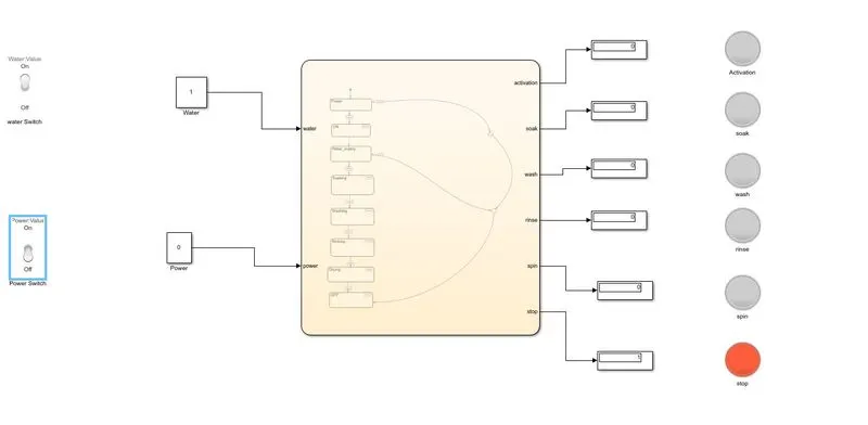
Different stages of washing machine working:
Soaking:
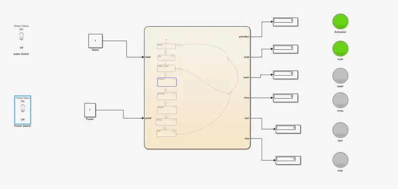
Washing:
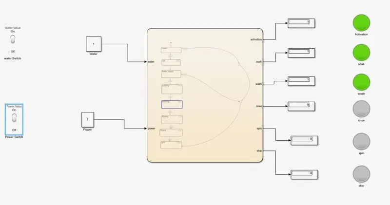
Rinsing:
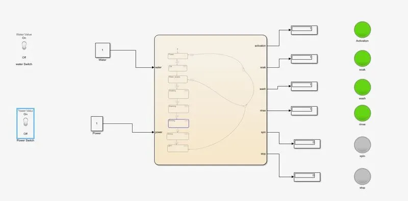
Drying:
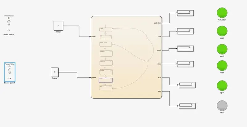
Part 2:
Aim:
Make a Simulink chart for the “Gear shift” logic as per conditions
Input Conditions given Gear-Shifting model:
Speed Range(kmph) Gear
0 to 15 1
16 to 25 2
26 to 40 3
41 to 60 4
Above 61 5
Blocks used in the gear shifting model:
- Slider:- The Slider block tunes the value of the connected block parameter during simulation.
- Constant Block :- Constantixed inputs provided to the stateflow chart.
- Display :- We have used the display block to show the vehicle is going at which gear for particular speed.
- Real-Time Synchronization Block:- This block uses to synchronize model execution to real time in normal mode.
- Scope:- This block is used to visualize output waveform.
- Vertical Slider Block :- This block is used so that it can deflect gear number according to the display block's output.
Stateflow Chart:
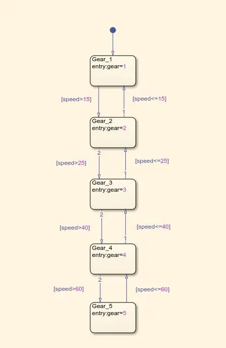
- Initially, we have created first state(Gear_1) and in this, we have given a condition such that if input speed>15 then the gear got shifted to second gear. That means, if (speed<=15) condition satisfied then the car remains in the first gear only.
- When the (speed>15 condition) got satisfied then the car got shifted to second gear(Gear 2 state). Then the car remains in the second gear until speed goes above 25 unit.
- When (speed>25 condition) got satisfied then the car shifted to third state(Gear_3). Further, if speed falls to 25 and below 25 unit, the car got again shifted to second gear.
- Furthermore, if (speed>40 condition) got satisfied then the car shifted to fourth state (Gear_4). Further, if speed falls to 40 and below 40 unit, the car got again shifted to third gear.
- Also, if (speed 60 condition) got satisfied then the car shifted to fifth state(Gear_5). Further, if speed falls to 60 and below 60 unit, the car got again shifted to fourth gear.
- If the speed remains to be higher/greater than 60 unit then car will remain in fifth gear only untill there is any drop in speed of the car.
Simulink Model:
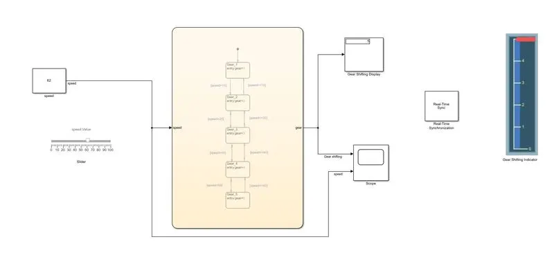
Google Drive File: https://drive.google.com/file/d/1CVM_tuJJ0ws6sRwREgvbAUNKYWC8LN2y/view?usp=sharing
Explanation:
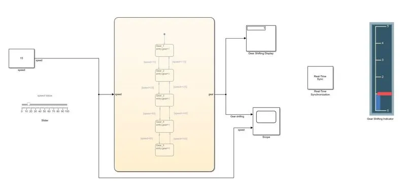
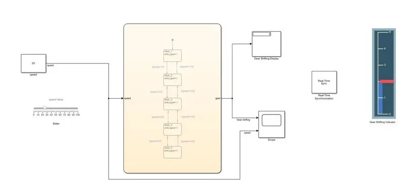
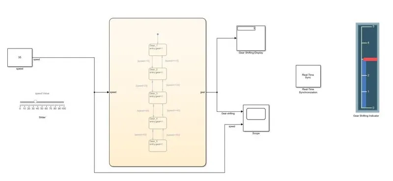
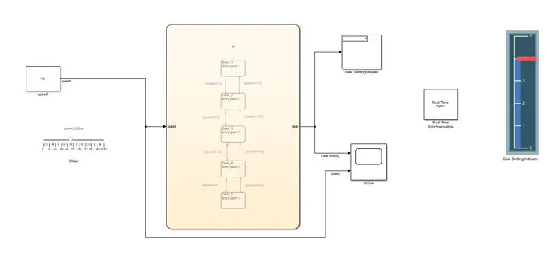
- Initially, we have taken Slider block so that we can vary our speed input during simulation. Instead of using simulation time as infinite time, we have used real-time kernel block i.e. Real-Time synchronization.
- We have connected the slider block to the constant block(speed) and that block is further connected to contol logic so that gear shifting of car can be achieved by varying the speed input.
- Hence, when we increase the speed by moving the slider then automatically as per our control logic and given condition, the corresponding gear number was displayed at the output. We have used display block at the output of control logic chart to record the gear number for particular instance of speed.
- Further, we have also used vertical gauge block and renamed as gear shifting indicator. We have internally connected that Gear shifting indicator block to display block so that gear number can be correspondingly deflected.
- Also, we have used scope block to visualise the output(i.e. Gear number & input i.e. Speed).
Gear 1:
Gear 2:
Gear 3:
Gear 4:
Gear 5:
Output Graph:
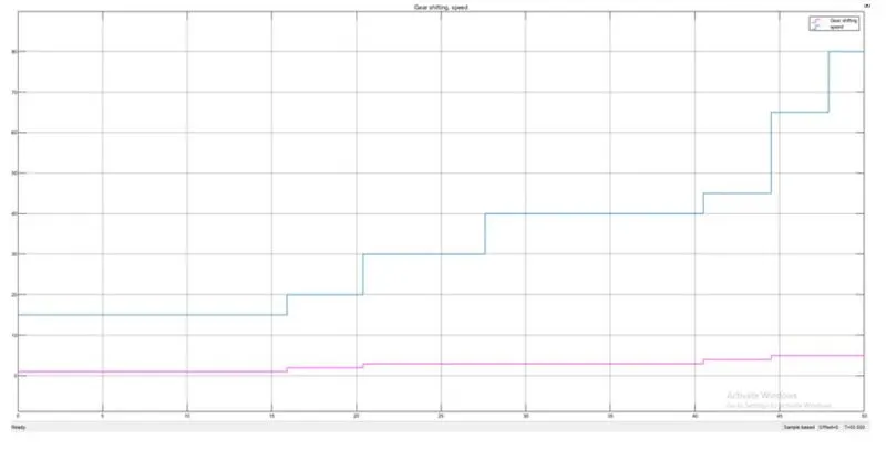
Conclusion:
From the above graph, we observed that the gear shift took place as per the given speed condition.