Week -2
AIM: TO simulate a doorbell and heater model using Simulink.
OBJECTIVE:
1. To observe the physical movement of the plunger by creating a situation where the switch is closed for 2 seconds and then released.
2. To use a thermistor to sense the temperature of a heater and turn on or off the fan as per below conditions.
Temperature Source: 20 °C from 0 to 10 seconds, 27 °C from 10 to 30 seconds, 23 °C from 30 to 50 seconds
Fan conditions: ON if the temperature above 25 °C, OFF otherwise
SOLUTION
PART 1: SIMULATION OF DOOR BELL
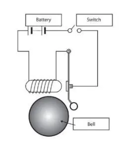
Simulink Model:
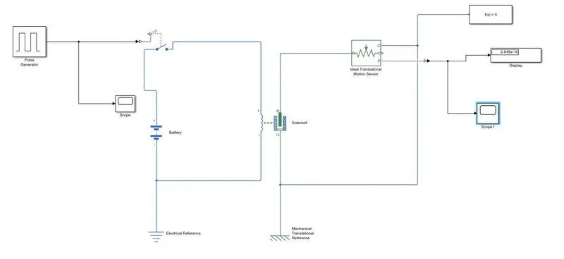
Google Drive: https://drive.google.com/file/d/11SQntjMeoWqAYzMk7a2Ypx5Hi6qXQZHm/view?usp=sharing
Procedure/Steps:
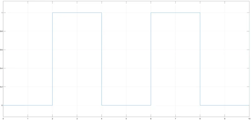
1. An input signal is given according to given conditions (Amplitude-1, Period 4 sec, Pulse Width -50%, Phase Delay-2 sec).
2. A Simulink-PS Converter is used to convert the input Simulink signal into a physical signal.
3. A switch is connected to the battery and solenoid respectively as shown. If the external physical signal PS is greater than the threshold, then the switch is closed, otherwise, the switch is open
4. Solenoid converts electrical signals to mechanical signals.
5. The Ideal mechanical translational motion sensor converts an across variable measured between two mechanical translational nodes into a control signal proportional to velocity and position.
6. A PS-Simulink Converter is used to convert the physical signal into a Simulink output signal.
7. The Solver Configuration block specifies the solver parameters that your model needs before you can begin the simulation.
GRAPH:
INPUT:
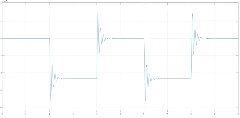
OUTPUT
For damping=0N/(m/s)
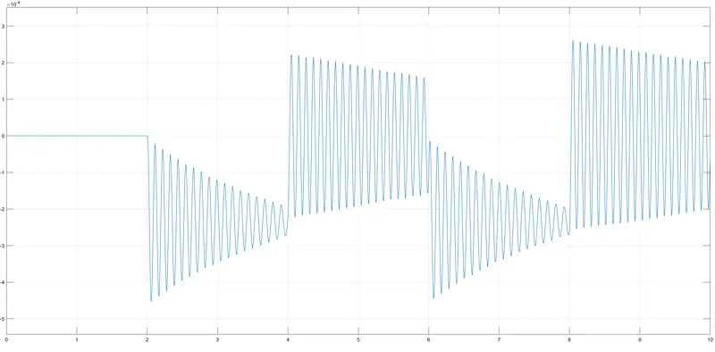
For damping=1N/(m/s)
PART 2: THERMISTOR BASED AUTOMATIC FAN
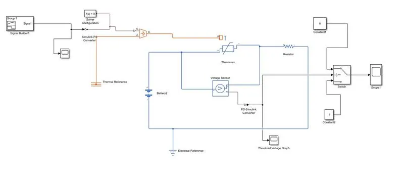
Simulink model:
Google Drive: https://drive.google.com/file/d/11SQntjMeoWqAYzMk7a2Ypx5Hi6qXQZHm/view?usp=sharing
Explanation:
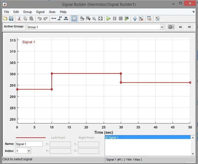
1. Initially, we have used the Signal builder block so that we can put our temperature source value as under,
= For 0-10 sec, temperature = 20 degree Celcius
= For 10-30 sec, temperature - 27 degree Celcius
= For 30-50 sec, temperature = 23 degree Celcius
2. Since, the controlled temperature source and thermistor block only takes values in Kelvin, hence we have converted those temperature values into kelvin, and accordingly, we have made the Signal builder block as follows;
3. Further, we have connected the Signal builder block to the Simulink-PS converter block since the controlled temperature source takes only the physical control signal as input. Further, we have connected output terminal B of the controlled temperature source to thermal port A of the Thermistor block.
4. Thereafter, we have taken the Thermistor block to sense the temperature of the circuit. Further, we have connected the positive terminal of the thermistor to the positive terminal of the battery. Here, we have used a battery block as a DC voltage source. Thereafter, we have connected a voltage sensor parallel to the thermistor block to measure the voltage across the circuit and convert those measured voltage values into a physical signal proportional to the voltage. We have also used a resistor block to provide resistance to the electric flow of current.
5. Due to this, Physical signal port V of the voltage sensor-generated threshold voltage for given temperature conditions. However, it is a physical signal. Hence, we have used a PS-Simulink converter to convert those physical signals into Simulink signals.
6. As per the fan conditions given in question states the fan should be on if the temperature goes above 25 deg. Celcius Le. (298.13 K). Hence, we have introduced one constant block resembling a temperature of 25 deg. celsius and then calculated the threshold voltage as (11.92) required to trigger the switch so that mentioned fan condition can be satisfied.
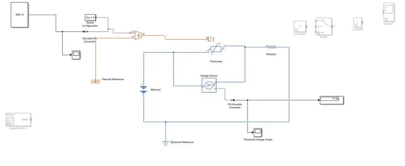
7. we have used scope block and connected it to the output port v of voltage sensor & PS-Simulink convertor to see the voltage graph given temperature conditions as follows: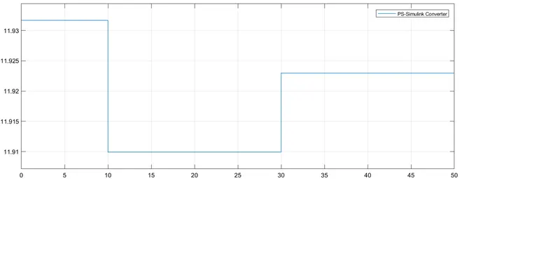
8. From the above graph, it was very evident that for time (0-10 sec), voltage is around 11.935 V at temperature 293.13 K. Further, it was observed that for time(10-30 sec), voltage is around 11.91 V at temperature 300.13 K and for time(30-50 sec), voltage is around 11.9225 v at temperature 296.13 K.
9. Hence, we can say that as soon as temperature increases in the circuit, voltage values decrease.
10. Further, we have connected the voltage signal to port 2 of the switch block. Here, we have given the threshold voltage value as 11.92 because as per fan condition, the fan should be on when the temperature goes above 25 deg. Celcius.
11. Switch block has a condition such that when control signal port U2 is greater than or equal to the threshold value, it passes through port 1 otherwise it passes through port 3
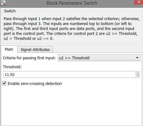
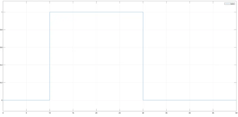
12. Hence, we can say that when the temperature value is greater than 25 deg. Celcius, voltage value will be less than threshold voltage value hence for that particular instance of the signal, the signal passes through port 3. Hence, for port 3, we have connected the constant block of value as '1' as true condition and the fan will switch on.
13. Further, when the temperature value is less than 25 deg. Celcius, voltage value will be more than threshold voltage value, hence for that particular instance of the signal, the signal passes through port 1. Hence, for port 1, we have connected a constant block of value as 0 as a false condition and the fan will be switched off.
14. Scope block has been connected to the output port of switch so that output graph can be observed.
Conclusion:
1. For the Doorbell challenge, we have given input as the time period for 2 seconds in the pulse generator to open & close the switch. When the switch is closed the solenoid block receives electrical power from the battery and the plunger moves from port R to port C to hit the bell & produce sound. The physical movement of the plunger is observed by using a translational motion sensor & physical output is converted into Simulink output model is displayed in the scope. By reducing the spring constant value and increasing the damping value, vibrations will be reduced.
2. For the Thermistor challenge, we observed that as soon as temperature increases in the circuit, voltage value got decreased. Hence, we have used this logic to operate fan conditions when the temperature is above 25 deg. Celcius, the voltage value is less than the threshold voltage, then it triggered the switch to operate true condition as I and fan get on otherwise it is off.