Control logic of washing machine and gear shifting mechanism using Stateflow (Week-4)
QUESTIONS
- Implement control logic of a “washing machine” using Stateflow as per given sequence:
- If the power supply is available, the system gets activated
- If the Water supply is not available, stop the process & indicate through LED
- Soaking time should be 200s followed by Washing time of 100s.
- Then rinsing happens for the next 20s & dryer runs for 50s.
After all the processes have completed turn on the finished LED.
- Make a Simulink chart for the “Gear shift” logic as per the below conditions:
Speed Range (kmph) Gear
0 to 15 1
16 to 25 2
26 to 40 3
41 to 60 4
Above 61 5
Give speed input while the simulation is running & display the gear number.
ANSWERS
ANSWER 1
#Aim
To implement the control logic of a washing machine using Stateflow as per the given conditions.
- If the power supply is available, the system gets activated
- If the Water supply is not available, stop the process & indicate through LED
- Soaking time should be 200s followed by Washing time of 100s.
- Then rinsing happens for the next 20s & dryer runs for 50s.
#Theory
A washing machine is a home appliance used to wash laundry. The term is mostly applied to machines that use water as opposed to dry cleaning or ultrasonic cleaners. The user adds laundry detergent, which is sold in liquid or powder form, to the wash water. Washing machines can be classified as follows:
- Semi-automatic washing machine: The semi-automatic is needed for your assistant to get the job done. Here, you will have to pour in the water manually and need to set up the timer, etc.
- Fully automatic washing machine: The fully automatic washing machines are more convenient and offer a great range of functionality. You get fully automatic functions that carry out the washing without any manual interference. They are a little more budget-friendly, and you spend a normal price to get actually purchase.
Fully automatic washing machines can further be divided into two types: -
- Front Load Washing Machine: You get a front door to put the load into the drum. The drum wash, rinse and spins the laundry. Here you see the different working principle, the clothes are tossing from one direction to the other, as the drum itself is moving. Most of the frontload washing machine uses agitator washing style to wash and rinse the clothes.
- Top Load Washing Machine: In a top-loading washing machine, you load the washing machine from the top. The drum here does not move from one direction to the other, but the base of the machine rotates and moves the clothes thoroughly. Here, the machine's base takes clockwise and anti-clockwise rotation, to fully wash the dresses.
#Different Processes in Washing machine
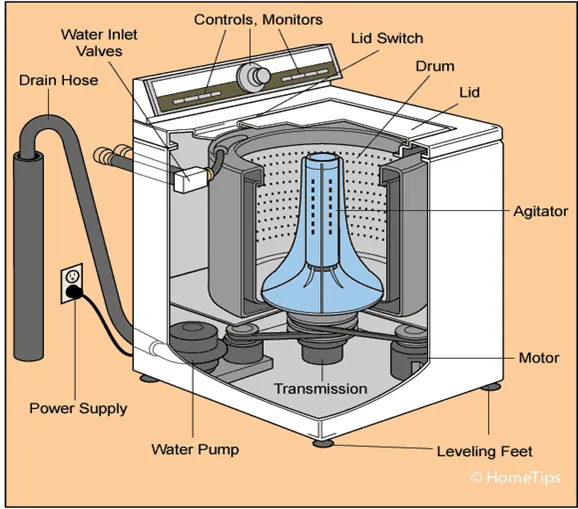
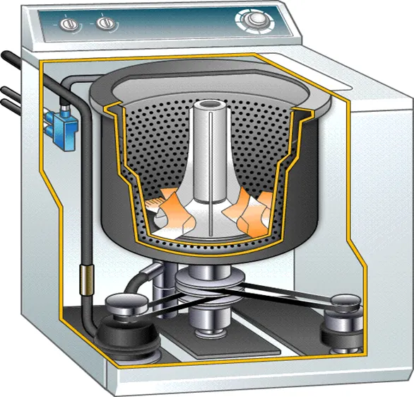
Rinsing - Clothes washers play out a few flushes after the fundamental wash to eliminate the greater part of the cleanser. Current clothes washers utilize less water because of ecological concerns; notwithstanding, this has prompted the issue of helpless flushing on many clothes washers on the market, which can be an issue for individuals who are touchy to cleansers. The Allergy UK site recommends re-running the flush cycle or rerunning the whole wash cycle without a cleanser. In light of grievances, many clothes washers permit the client to choose extra flush cycles, to the detriment of higher water utilization and longer process duration. Bosch for instance, in its hypersensitivity wash program, consolidates an extra 3-minute flush cycle with water of in any event 60 degree Celsius to flush off cleanser deposits and any allergen.
Spinning - Higher twist speeds, alongside bigger tub widths, eliminate more water, prompting quicker drying. Then again, try not to press can be gotten by not utilizing a twisted cycle in the clothes washer. In the event that a warmed garments dryer is utilized after the wash and twist, energy use is decreased if more water has been taken off from garments. Be that as it may, quicker turning can wrinkle garments more. Additionally, mechanical wear on direction increments quickly with rotational speed, diminishing life. Early machines would turn at 300 rpm and, due to the absence of any mechanical suspension, would frequently shake and vibrate.
Soaking - The washer did not immediately wash when added the detergent, but the washer will be intermittent rotation, because there has a soak time, and the washing machine automatically starts washing when the soak time has elapsed.
Dryer - A washer-dryer is a washing machine with an inbuilt tumble dryer, so if you need to dry clothes quickly, it’s a good option as it both washes and dries your clothes in the same cycle – so all you need to do is remove the clothes from the machine and they’re ready to wear.
#Simulink Model of the washing machine
#Stateflow
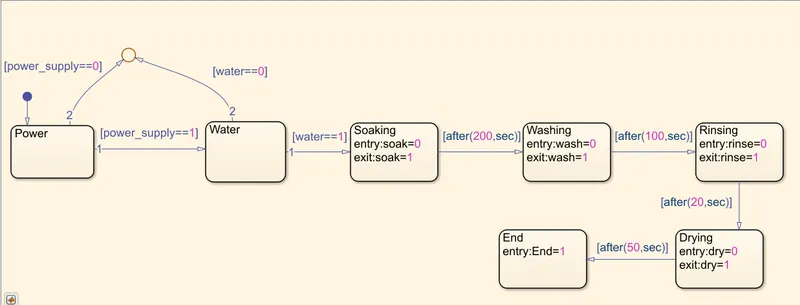
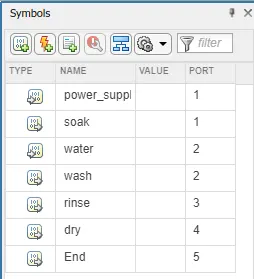
Control Logic and Explanation
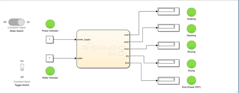
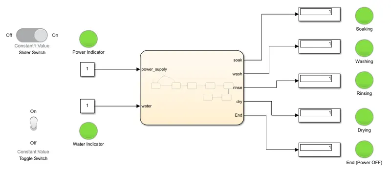
- For making the model we have to create a Stateflow chart with power supply, water, soak, Wash, Rinse, Dry and end of the cycle.
- To start with the charts we require a breakpoint added with chart Power (we can name the chart with any name to define the chart for our reference).
- From power to water we make a loop with conditions: - if power is 1 the flow of current goes to engage the water and when the water has 1 condition the washing machine cycle runs from soak till the end. Flow chart notation uses connective junctions to represent common code structures like loops and (if-else) constructs without the use of states.
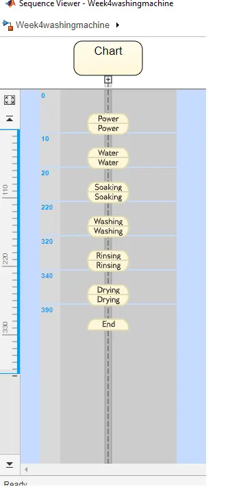
- I have given entry soak=O and exit soak=1 with this we set breakpoint flow of water is for 200 seconds and once it reaches above 200 seconds it will go to next process washing. The washing, rinsing and drying are set as per the given timeframe.
- Here I have input end=1, so that the lamp will indicate when the display is one.
- After creating the charts we have to check the input and output through the symbol pane tool which is visible on the left side of the chart page. In the type column, we have to define the input and output. Here, power supply and water are given as input data. Soak, Wash, Rinse & Dry are given as output data.
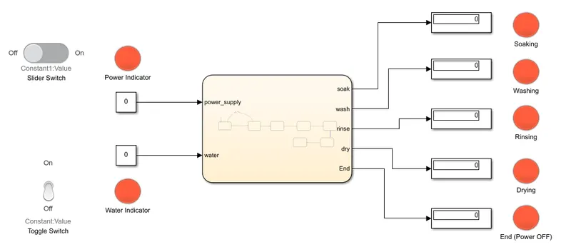
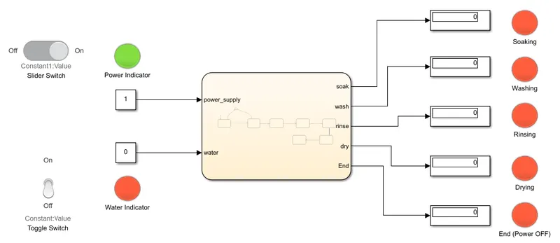
- After giving the input and out we will be connecting the power and water to two constant blocks which are connected to slider switch and toggle switch. All the five outputs are connected to their respective displays and lamps to indicate the washing cycle.
#Result
Power supply OFF and water OFF
Power supply ON and water OFF
Power supply ON and water ON
Output -Sequence Viewer
ANSWER 2
#Aim
Make a Simulink chart for the “Gear shift” logic as per the below conditions:
Speed Range (km/h Gear
0 to 15 1
16 to 25 2
26 to 40 3
41 to 60 4
Above 61 5
#Theory
Gear Transmission
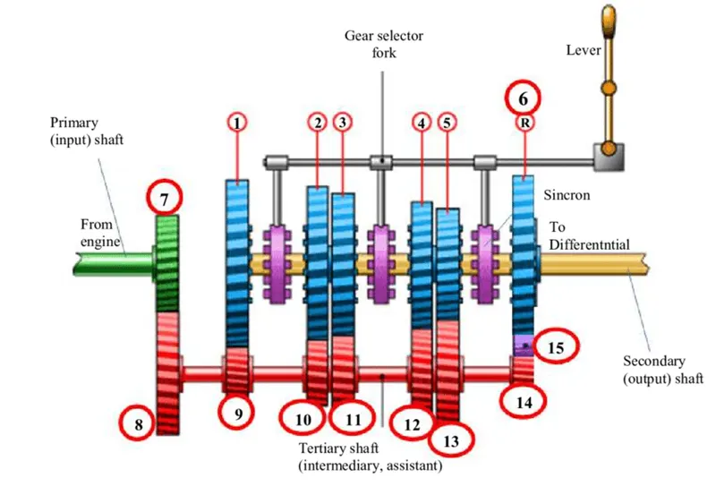
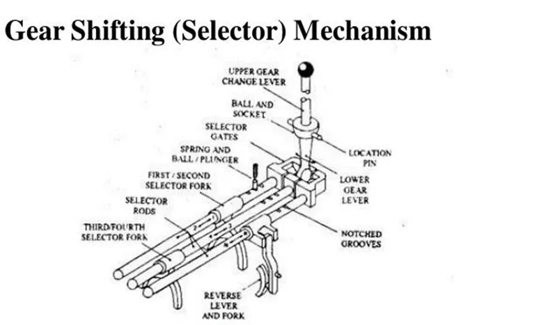
The gear shifter is responsible for physically engaging the gears on the output shaft, locking them in place so that they turn the shaft and send torque to the drive wheels. This is where visuals are really useful. Moving the shifter into position engages the gear selector forks. The gear shifter and clutch pedal are the two inputs by which a driver operates a manual transmission, though if we're being technical the shifter is the only piece of this whole puzzle that is operated manually. The transmission housing contains three shafts interacting with one another. One of them is attached to the engine (the input shaft), one is attached to the differential (the output shaft), and the third shaft, often called the layshaft or the countershaft, interacts with the other two via a system of gears. While your car is on, the engine shaft is always turning, even while stopped. It has to keep going otherwise the engine doesn't work.
Working of gear transmission
In a gearbox, the tertiary (counter) shaft is mashed to the clutch with the use of a couple of gears. So, the countershaft is always in running condition. When the tertiary shaft is brought in contact with the main shaft by the use of meshing gears, the main shaft starts to rotate according to the gear ratio. When the driver wants to change the gear ratio, simply press the clutch pedal which disconnects the tertiary shaft with the engine and connects the main shaft with the tertiary shaft by another gear ratio by use of gearshift lever.
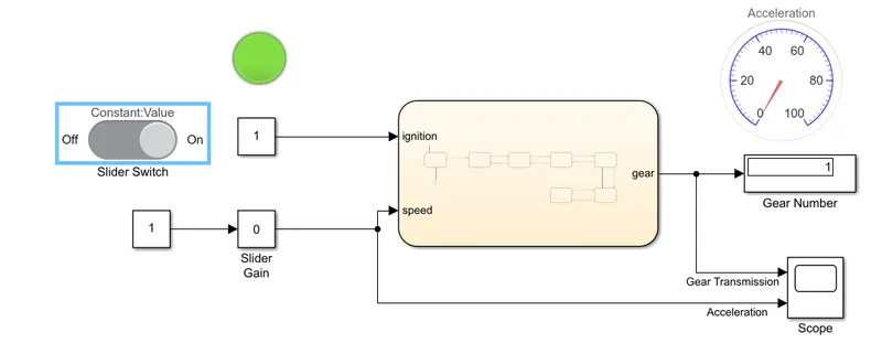
#Simulink Model of the Gear Shift mechanism
#Stateflow
Control Logic and Explanation
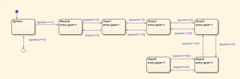
- Create a chart block for defining the stateflow as per the given conditions.
- Inside it, the circular junction is to terminate the signal flow and return a null value.
- If ignition is OFF i.e., 0, the process is terminated at the junction else 1 is carry forwarded.
- If speed is less than 0 the flow is terminated and gear 0 is activated at the junction else 1 is carry forwarded.
- If speed is greater than or equal to 0 and less than or equal to 15, the flow is terminated and gear 1 is activated.
- If speed is greater than 15 and less than or equal to 25. the flow is terminated and gear 2 is activated.
- If speed is greater than 25 and less than or equal to 40, the flow is terminated and gear 3 is activated.
- If speed is greater than 40 and less than or equal to 60, the flow is terminated and gear 4 is activated.
- If speed is greater than 60, the flow is terminated and gear 5 is activated.
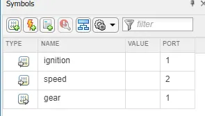
- Define ignition and speed as inputs whereas speedometer, scope and gear number display as outputs.
- Connect the chart block with constant blocks for ignition and speed inputs. Input switches connected to them are slider switch and a slider gain is to obtain variable speeds. Attach lamp to observe the ignition ON/OFF condition.
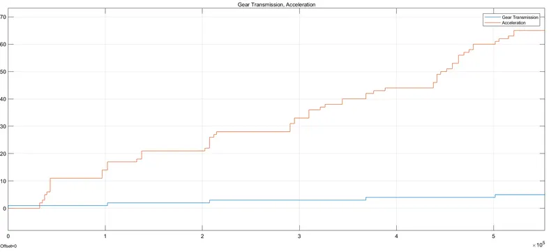
- A common scope block is connected to obtain the output plot and observe the speed numerically.
#Results
- Ignition ON; Speed 0-15; Gear=1
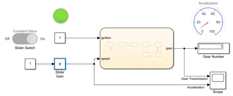
- Ignition ON; Speed 16-25; Gear=2
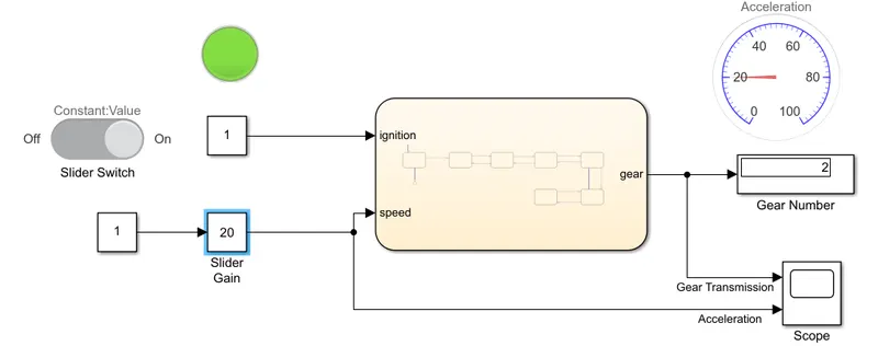
- Ignition ON; Speed 26-40; Gear=3
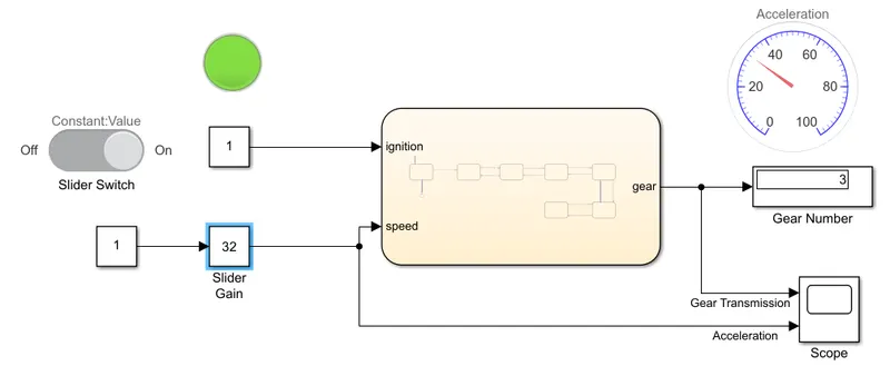
- Ignition ON; Speed 41-60; Gear=4
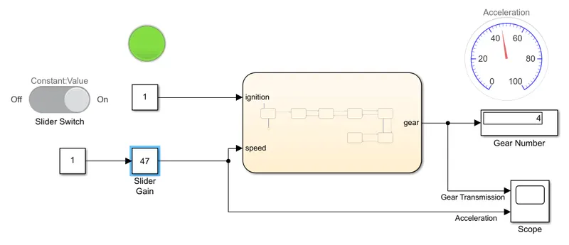
- Ignition ON; Speed above 60; Gear=5
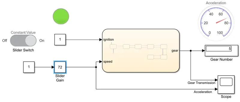
# Output
The following graph is obtained from the scope. It shows the gear number for the corresponding speed.