Simulink Model of Doorbell and Thermistor control of Fan (Week-2)
QUESTIONS
- Make a Simulink model of Doorbell using a solenoid block with the following details:
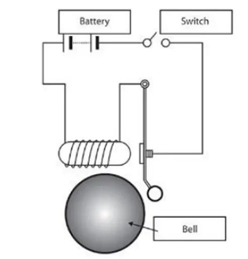
In the above arrangement, when the switch is closed the electromagnet receives electrical power from the battery and pulls the metal arm to hit the bell producing sound.
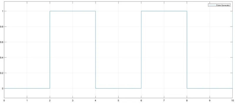
Create a situation where the switch is closed for 2 seconds and then released. Observe the physical movement of the plunger.
- Use a thermistor to sense the temperature of a heater & turn on or turn off the fan as per the below conditions:
Temperature source: 20 °C from 0 to 10 seconds, 27 °C from 10 to 30 seconds, 23 °C from 30 to 50 seconds.
Fan conditions: ON if the temperature above 25 °C, OFF otherwise.
ANSWERS
ANSWER 1
#Aim
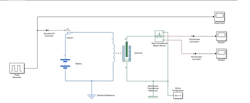
Our aim is to make a doorbell with Simulink and observe the movements of the plunger when the switch is closed for every 2 seconds and then released. The graph of the plunger position with time is obtained on Scope 2 and the graph of the velocity of the plunger with time is obtained on Scope 1.
#Simulink Block Diagram
Solenoid
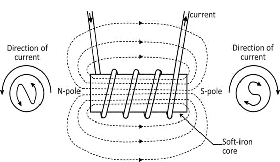
A solenoid is a three-dimensional structure of a wire. When the wire is wrapped around a metallic block in a coil and electricity is passed through it, it has some special magnetic properties. Electromagnetic induction makes it an electromagnet that can be turned on or off. The side in which the current appears to be passing clockwise, is the South Pole and the side in which the current appears to be passing anti-clockwise is the North Pole. The solenoid works as a bar magnet and therefore has many uses.
Doorbell
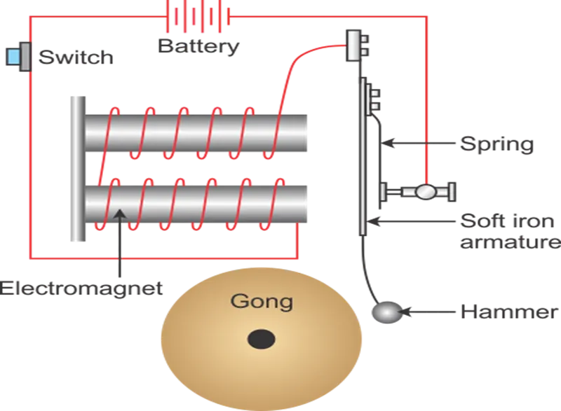
An electric doorbell is a simple circuit that triggers a sound on the completion of the circuit by pressing the button. When the switch is pressed, the circuit loop is complete which causes the current to flow through the circuit. The arm which strikes the gong is connected to the spring at one end and an iron ball at the other end. This is called a hammer or striker. The arm is attached to an iron strip which is attached to the electromagnet when the circuit is complete and the current flowing through it.
#Simulink Blocks Used
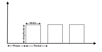
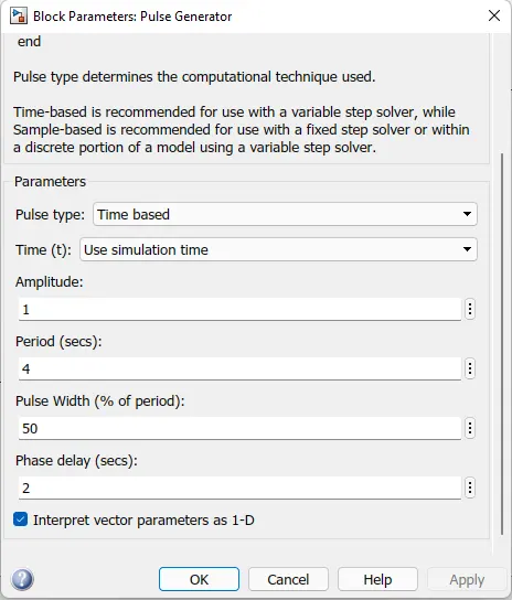
- Pulse Generator – This block generates square wave pulses at regular intervals. The block wave parameters such as Amplitude, pulse width, period and phase delay determine the shape of the waveform.
- Simulink-PS Convertor - This block is used to convert Simulink input signal into physical signal.
- PS-Simulink Convertor - This block is used to convert physical signal to Simulink output signal.
- Switch - The block represents a switch controlled by an external physical signal. If the external physical signal PS is greater than the threshold, then the switch is closed, otherwise the switch is open.
- Battery – It provides voltage to the system.
- Solenoid – Solenoid converts electrical signal to mechanical signals. This block is used to pull the metal arm to hit the bell.
- Ideal translational Motion Sensor – This block represents a device that converts an across variable measured between two mechanical translational nodes into a control signal proportional to velocity and position.
- Electrical reference - This block represents an electrical ground. It provides reference point to the electrical signal.
- Mechanical reference - This block provides reference point to the mechanical ports.
- Solver configuration – This block defines solver settings to use for simulation.
- Scope – This block is used to view the output from the translational motion sensor. It also gives the graphical representation i.e., to view the characteristics of a property with respect to time.
#Input Signal
#Output
The simulation is run for 10 seconds and the following graphs were obtained.
1) Scope 2 output: Graph of Position of the plunger at each time it triggers
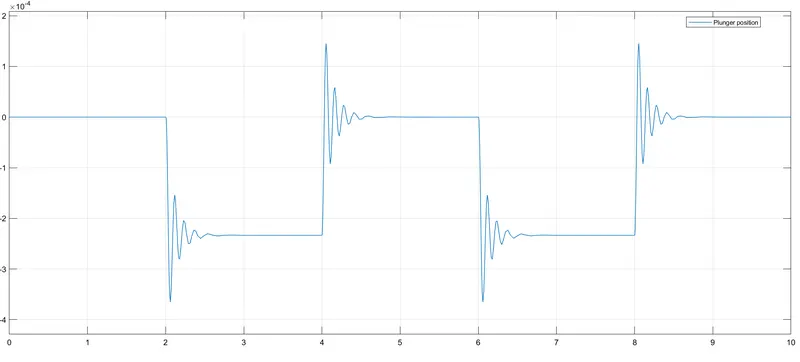
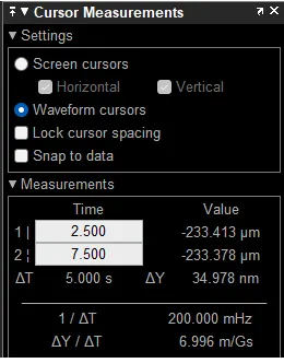
- The above graph determines the position of the plunger at the start of 2nd second and end by the 4th When the piston moves back, it again hits the other end, vibrates and produces another bell sound and remains in its position until the next pulse is passed. This repeats till the 10 seconds.
- At the start of 2 seconds the plunger moved from initial position where the initial position is set as zero to -233.413 micrometers. At the end of 4 seconds the circuit breaks, the plunger moves back to initial position i.e., zero position where it again hits the other end metal bar with force and produces another vibration wave.
- Changing parameters such as spring constant and damping coefficient will result in smoother motion.
- Two full cycles are shown here.
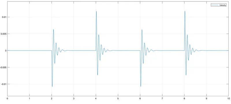
2) Scope 1 output: Graph of velocity of the plunger at each time it triggers
#Conclusion
- Thus, it is observed that at every two seconds there is vibration in the plots which shows that the plunger moves down and hits the bell. The bell is rung and the conditions are satisfied.
ANSWER 2
#Objective
To make a Simulink model which uses a thermistor to sense the temperature of a heater and turn off/on the fan as per the given conditions: -
Temperature source: 20 °C from 0 to 10 seconds, 27 °C from 10 to 30 seconds, 23 °C from 30 to 50 seconds.
Fan conditions: ON if the temperature above 25 °C, OFF otherwise.
#Simulink Block Diagram
Thermistors
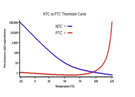
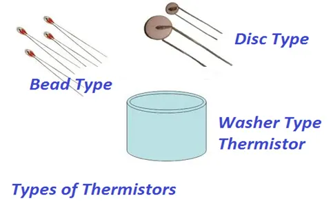
Thermistor is a temperature sensing element made up of semiconductor material which exhibits a large change in resistance proportional to the small change in temperature. Thermistors are of two types:-
- Positive temperature coefficient thermistor, PTC whose resistance increases with increase in temperature.
- Negative temperature coefficient thermistor, NTC whose resistance decreases with increase in temperature.
Thermistor acts as a resistor with a high and negative temperature coefficient of resistance. Due to this property of high sensitivity that is huge resistance change for a small change in temperature, the thermistor is mainly applicable in precision temperature measurements in a low temperature range. It works on a principle that when a constant current flowing through the resistor and its changing resistance due to change in temperature is measured as a voltage drop across it.
Thermistor resistance-temperature relationship can be dR=K* DT, where K is temperature coefficient, dR is change in resistance and dT is change in Temperature.
The negative temperature coefficient allows the thermistor circuit to detect minute changes in temperature which could not be observed by the other thermocouple circuits.
Resistor
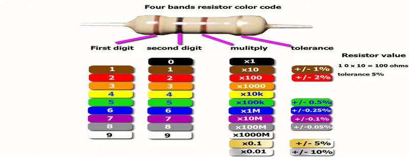
Resistor is an electronic component that limits or regulates the flow of electric current in an electronic circuit. These resistors are used to provide a specific voltage for an active device such as a thermistor which is also a resistor.
The resistance towards the flow of current will result in voltage drop R=V/l where R is Resistance, V is Voltage, I is current.
Electric current can be calculated by measuring the voltage drop over a precision resistor with a known resistance which is connected in series with the circuit. Resistors regulates current in the circuit to the required parameter. The temperature-resistance characteristic of a thermistor is non-linear and cannot be characterized by a single coefficient.
Controlled Temperature Source
The Controlled Temperature Source block represents an ideal source of thermal energy that is powerful enough to maintain specified temperature difference across the source regardless of the heat flow consumed by the system. Connections A and B are thermal conserving ports corresponding to the source inlet and outlet, respectively. Port S is a physical signal port, through which the control signal that drives the source is applied.
Voltage Sensor
The Voltage Sensor block represents an ideal voltage sensor, a device that converts voltage measured between two points of an electrical circuit into a physical signal proportional to the voltage.
Controlled Voltage Source
The block represents an ideal voltage source that is powerful enough to maintain the specified voltage at its output regardless of the current passing through it. The output voltage is V = Vs, where Vs is the numerical value presented at the physical signal port.
DC Motor (Electro-mechanical convertor)
Electro mechanical converter converts electrical energy to mechanical energy or mechanical energy to electrical energy via the medium of magnetic field or electrical field. When the conversion takes place from electrical to mechanical, the device is called motor. When the conversion takes place from mechanical to electrical then the device is called generator.
In our model we need to convert electrical energy source to mechanical energy source to run the fan which happens in the medium of electromagnetic field. When the conductor is allowed to move in a magnetic field, the voltage is induced in the conductor. When a current carrying conductor is placed in a magnetic field, then a mechanical force is experienced by the conductor. When such conductors are placed on the rotor which is free to move, the electromagnetic torque produces on the rotor and that torque is transferred to the shaft of the rotor which can be utilized to drive the mechanical load. Since the conductor rotates in the magnetic field, a voltage is induced in each conductor. The rotor is driven by prime mover, the voltage is induced in the rotor conductor. When there is a voltage difference the current flows continuously through the conductor and produces magnetic field. If the electric current or load via switch is allowed to pass through the winding of the motor, electric power is delivered to the load which is a fan in our model. The current flowing through the conductor will interact with the magnetic field to produce a reaction torque, which will tend to oppose the torque. The motor starts rotating and an ideal translational motion sensor is connected to the load so that the velocity of motor is measured and displayed in the scope block.
#Working Principle
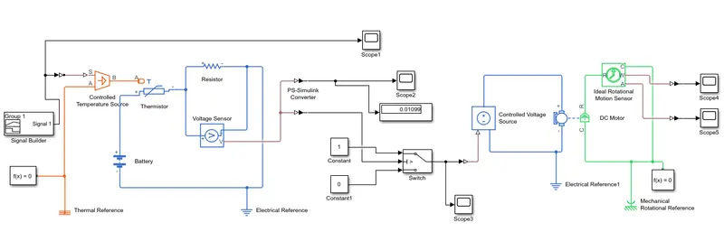
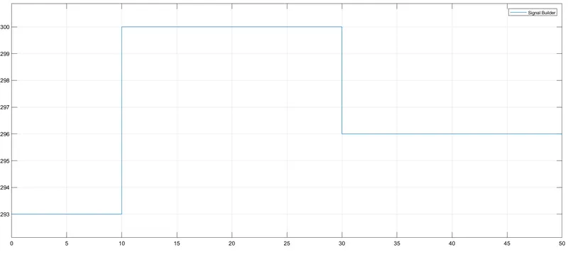
Using Signal Builder block a pulse is generated, which is range of temperature at different time periods (Total time - 50 seconds). This signal is given to the thermistor through controlled temperature source block. Two inputs were given to the thermistor, one is the thermal input from controlled temperature source and other one is electric current from the battery.
Due to the property of NTC thermistor, when temperature increases the resistance decreases. So, more charge carriers nothing but electrons that are available tends to conduct more current. In our model the display shows the value of voltage drop in negative values means more current flows through the conductor which is not desired. So, in order to regulate the current, we connect a resistor in series with the thermistor such that the required voltage parameter is maintained. The display shows the desired value of voltage and is sent as input to the switch control. If the value is more than zero, the switch will change to ON mode that means the circuit closes and current is passed to the DC motor. If the voltage value is less than zero, the circuit opens and the switch will be in OFF mode. No current is supplied to the DC motor.
DC motor plays a role of fan which is used to bring down the temperature of heater which we considered here with a controlled temperature source block for this model. Now when the current passes to the DC motor, electromagnetic field generates over the winding coil. Due to this the voltage is induced in the conductor and current flows through controlled voltage source until the switch is ON. When the rotor is placed in the magnetic field, it receives electromagnetic force and starts rotating. Here the mechanical source is fan which starts rotating until the temperature of heater decreases. Ideal translational motion sensor block is connected to motor by which we can take the values of velocity and angular displacement of fan and the graphs in scope block.
#Input Signal
Firstly, we have to convert the temperature degree Celsius (°C) into Kelvin (K)
|
Sr. No. |
At position |
Time (second) |
Temperature (Kelvin) |
|
1 |
At point 1 |
0 second |
293 K |
|
2 |
At point 2 |
10 second |
293 K |
|
3 |
At point 3 |
10 second |
300 K |
|
4 |
At point 4 |
30 second |
300 K |
|
5 |
At point 5 |
30 second |
296K |
|
6 |
At point 6 |
50 second |
296 K |
Signal Builder block is used to input the values as per given conditions.
#Output and Observations
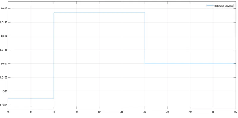
Scope 2: Voltage graph
The Threshold voltage value is obtained from the graph corresponding to temperature of 25 °C (298K) – 0.12V.
Scope 3: Output from switch
Take the threshold voltage value and pass it to the switch. The switch checks the value depending on the criteria for passing the input (u2> threshold). From the Graph, we can conclude that when the temperature is 20°C (293K), the fan was off for 10 second, when the temperature reached above 25°C (298K) the fan gets turn on for the next 20 second, and when the temperature again reaches to 23° Celsius (293K) fan gets turn off.
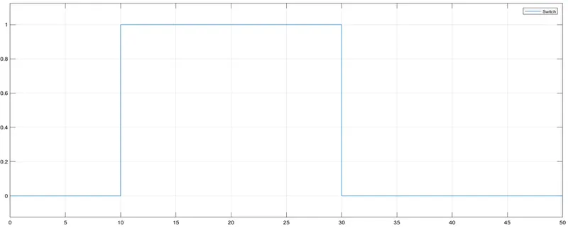
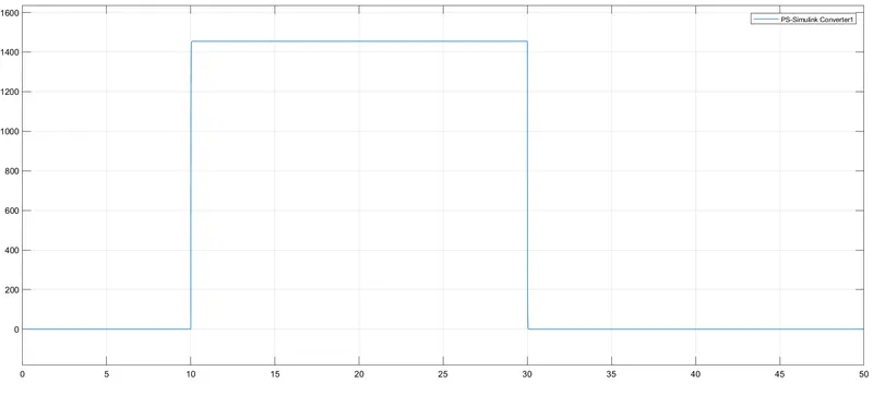
Scope 4: Velocity Output
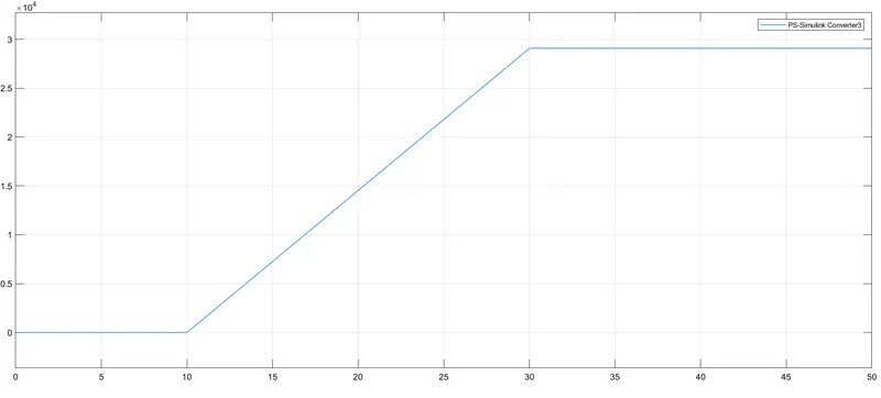
Scope 5: Angular Displacement Output
#Conclusion
The thermistor model was created and executed. We were able to switch ON the fan at a particular temperature as per the given conditions.