Week - 4
1.
Operation Procedure of a Washing Machine:
A Washing Machine/Washer is a sophisticated contraption used to ease/eliminate the process of manual washing. A fully automatic washing machine is used to demonstrate the control logic of the device. A washing machine undergoes various states of functions to ensure thorough cleansing of clothes; like Soaking, Washing, Rinsing and Drying with/without repetition.
Parameters:
- If the power supply is available, the system gets activated
- If the Water supply is not available, stop the process & indicate through LED
- Soaking time should be 200s followed by Washing time of 100s.
- Then rinsing happens for next 20s & dryer runs for 50s
Blocks Used:
1. Constant Block
2. Display Block
3. Lamp
4. Chart (Stateflow)
Layout:
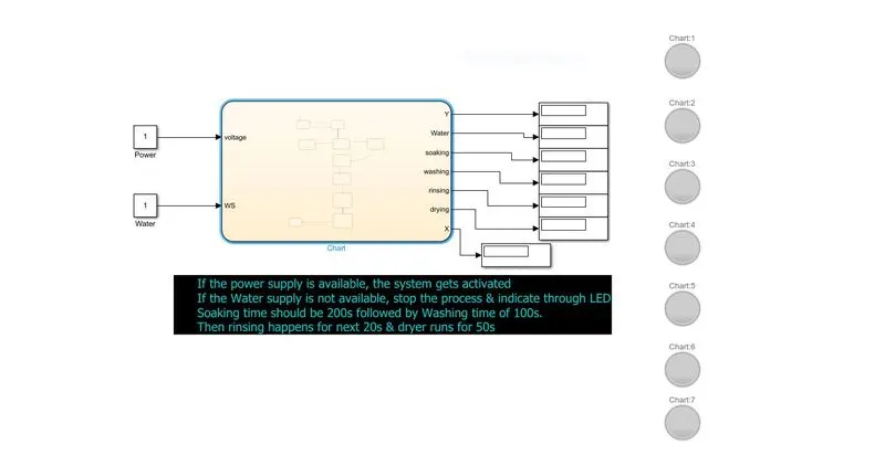
Stateflow Diagram:
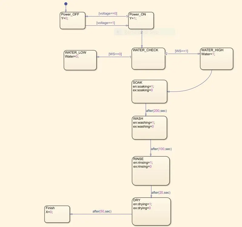
Parameter Implementation:
i) If the power supply is available, the system gets activate and If the Water supply is not available, stop the process & indicate through LED:
The Y variable denotes the presence of power. In the below diagram, The Power value is set as 1 which denotes the presence of power supply and the Water value is set as 0 denoting the availability. The below lamp indications show that the system has turned on due to the presence of power whereas the other processes are at halt due to unavailability of water.
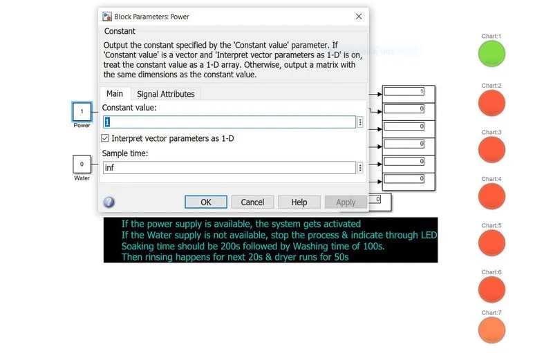
ii)Soaking time should be 200s followed by Washing time of 100s.:
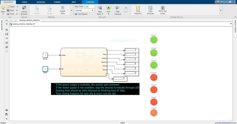
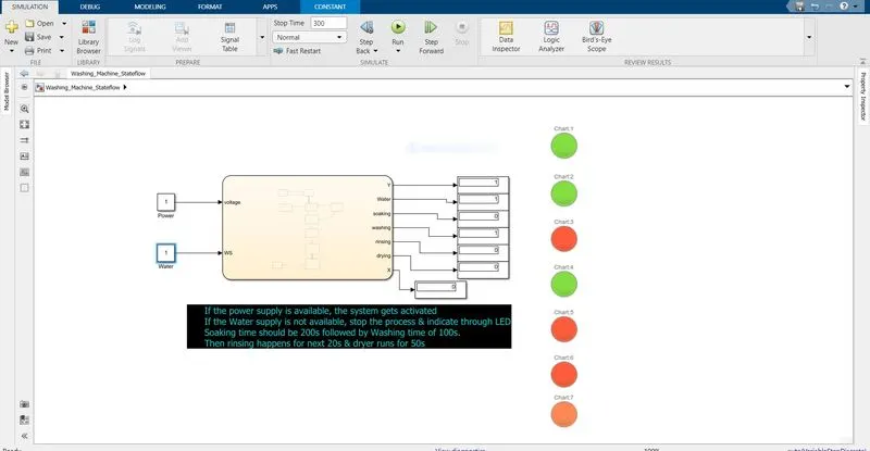
The Water value is set to 1 to start the washing process. Initially, the simulation is run for 200s and lamp (chart 3) corresponding to soaking is lit green indicating the process is happening. Secondly, The Simulation is run for 300s, which triggers the washing process and Chart 4 lamp is lit green. The chart 3 lamp is unlit due to the fact that soaking and washing cannot happen simultaneously.
Soaking:
Washing:
iii) Then rinsing happens for next 20s & dryer runs for 50s:
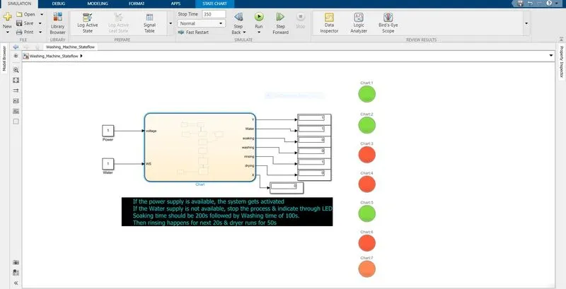
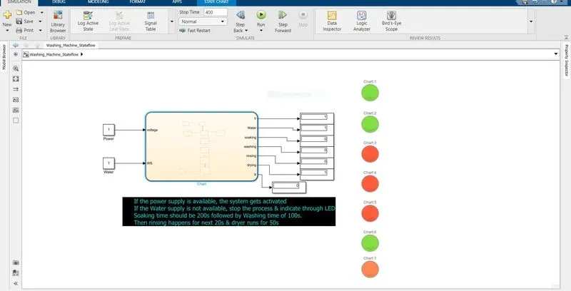
Similar to previous steps, The Rinsing and drying cycles are also simulated
Rinsing:
drying:
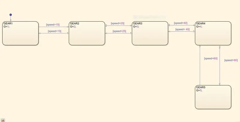
2) Gear Logic:
A Gear system is simulated to denote the change of gear in correspondence to varying speeds. The parameters for gear change is given below:
Parameters:
Speed Range(kmph) Gear
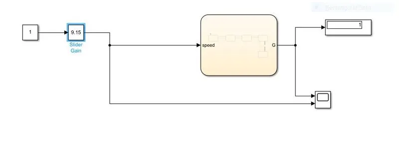
0 to 15 1
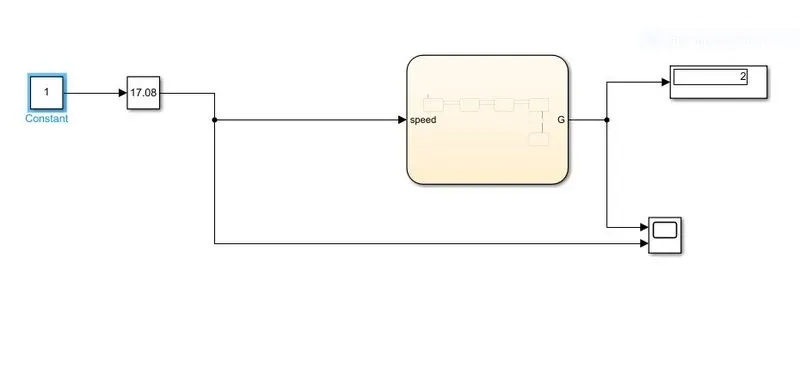
16 to 25 2
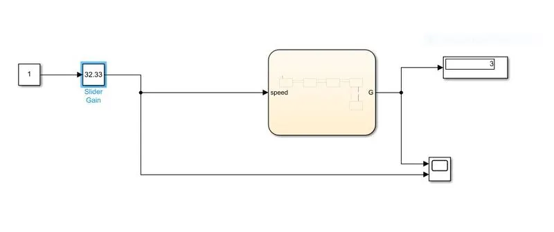
26 to 40 3
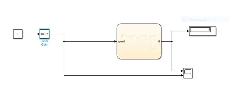
41 to 60 4
Above 61 5
Blocks Used:
1. Constant
2. Slider Gain
3. Chart (Stateflow)
4. Display
5. Scope
Brief:
A Slider Gain is used to vary the speeds such that the gear is changed by the logic implemented in the state flow. Find the below images displaying change in gear for corresponding speeds according to the parameters.
Gear 1:
Gear 2:
Gear 3:
Gear 4:
Gear 5:
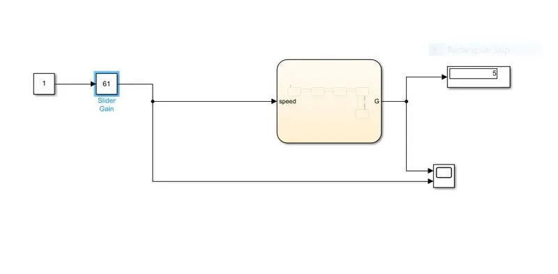
Stateflow Diagram: