Week -2
1.
Aim:
To create a Doorbell model using a solenoid block and observe its functionality by observing the plunger position when the switch is closed and release for 2 seconds.
Blocks Used:
1. Pulse Generator
2. Switch
3. Battery
4. Solenoid
5. Electrical Reference
6. Translational Motion Reference
7. Ideal Translational Motion Sensor
8. Solver Configuration
9. PS-Simulink/Simulink-PS Converters
10. Scope
11. Display
Function of a DoorBell:
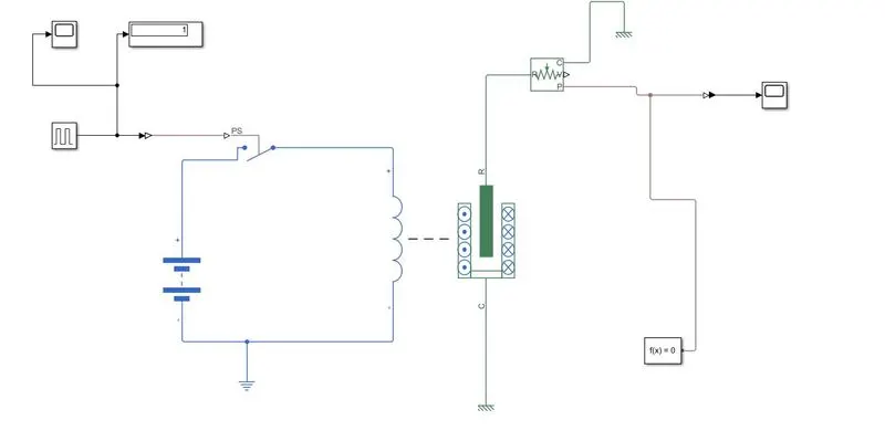
The governing principle of a Door Bell is Electromagnetism. The Solenoid helps the contact arm (Plunger) that comes in contact with a metal bell whenever there is a passage of current. The Solenoid acts as an electromagnet, such that it generates a magnetic field whenever a current flows through the coil. The switch is set up in a way that it operates in a regular interval of 2 seconds. The plunger position is observed to determine the functioning of the door bell. The plunger hits the bell whenever current flows through the circuit (Magnetisation) and goes back to its original position (Demagnetisation) when the current stops flowing. The repeated action of passage/blockage of current to the solenoid results in continuous striking on the bell by the contact arm.
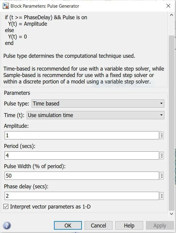
The Input parameters are provided below in such a way that the current passes for a duration of 2 second:
The below model shows the working of a Door Bell using a Solenoid:
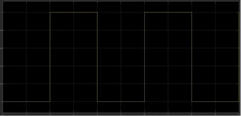
The Input is graphically represented in such a way that a pulse of current is sent through the circuit for two seconds:
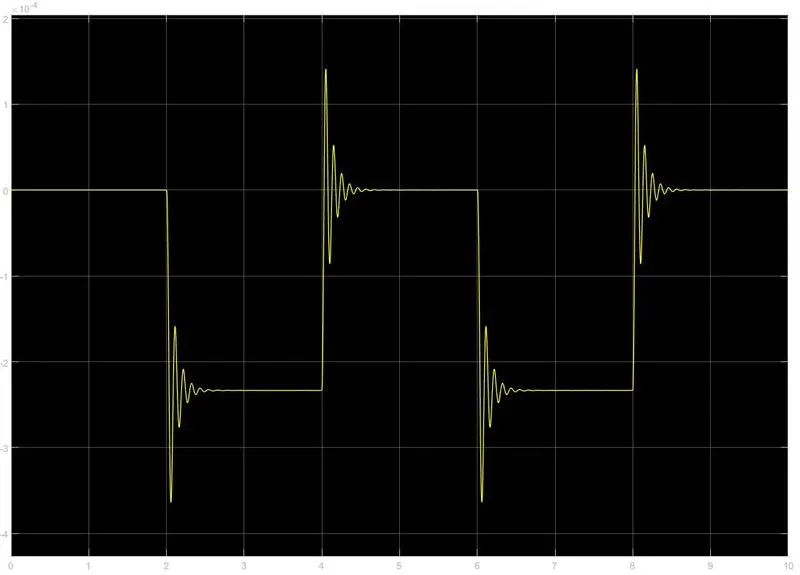
The Output shows the position of the plunger whenever a current passes:
2.
Aim:
To control a fan using a thermistor, in such a way that current passes through the circuit according to the temperature sensed by the thermistor.
Simulation Parameters:
Temperature source: 20 °C from 0 to 10 seconds, 27 °C from 10 to 30 seconds, 23 °C from 30 to 50 seconds
Fan conditions: ON if the temperature above 25 °C, OFF otherwise
Blocks Used:
1. Repeating Stair Sequence
2. Controlled Thermal Source
3. Ps-Simulink/Simulink-Ps Converters
4. Thermistor
5. Resistor
6. Voltage Sensor
7. Switch
8. Solver Configuration
9. Battery
10. Electrical Reference
11. Scope
Functioning of Thermistor Controlled Fan:
1. According to the input parameters, A Repeating Sequence is built by converting the values from DegC to K as the Thermal Controlled Source accepts K as input.
2. The Controlled Source provides the temperature input to the Thermistor.
3. The circuit has to be triggered, so a battery is introduced and connected to the thermistor. A resistor block is introduced to amplify the voltage that is yet to be sensed by a "Voltage Sensor".
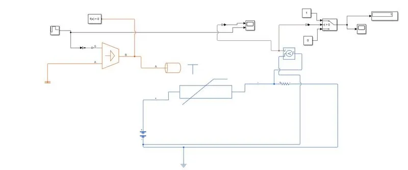
4. A Switch is placed in such a way that, if the voltage sensed is positive (@ 25 degC), the switch is turned on (Display =1); And if the voltage sensed is negative, the switch is turned off (Display =0).
The below picture explains the model of Thermal Controlled fan:
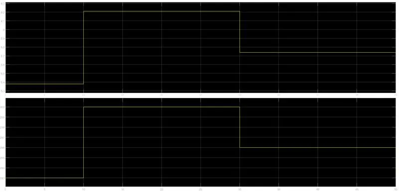
The below picture represents two graphs; Temperature Input vs Voltage. Observations show that the voltage across the circuit is directly proportional to the temperature input (@25 degC). It affirms the fact that the switch is turned on at 300 K (25 degC).