Week - 4
Implement control logic of a “washing machine” using Stateflow
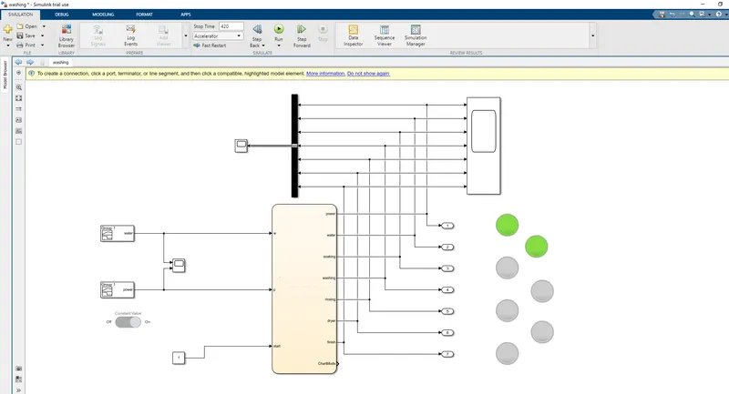
when the power supply and water available the system gets activated
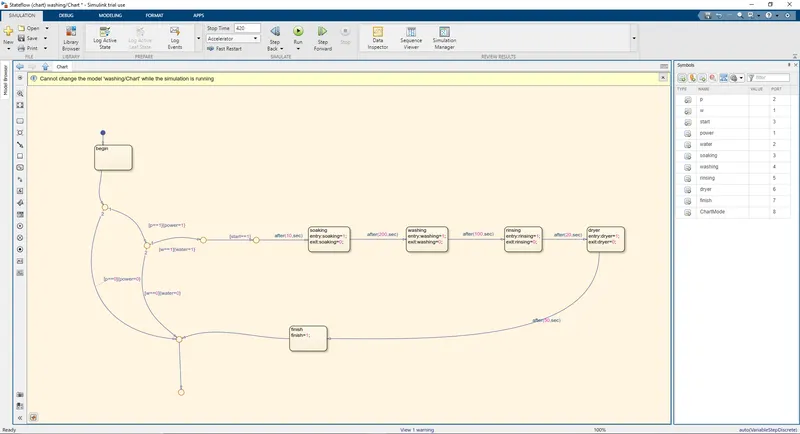
chart
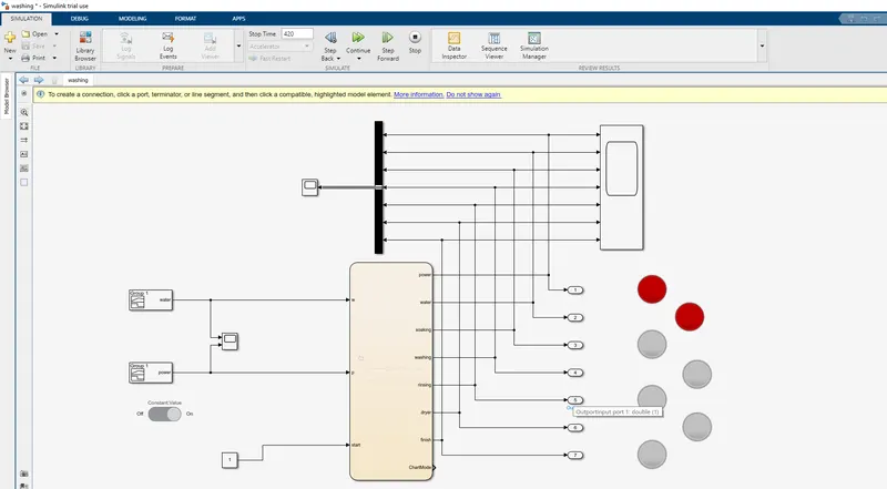
when the water supply is not available
explaination -
1- power and water supply is given as input signal as shown in the block above.the power is turned on after 10 sec and water is turned after 20 sec.
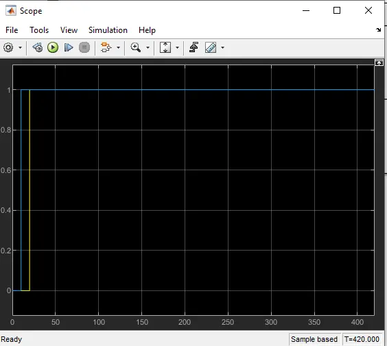
blue liine represent power and yellow line water.
2-the machine is turned on with help of switch which is connected to a constant which interchanges between 1 and 0.
3-if the water is not available the process is stoped as water indicator shows red light.
4-when the water is available thesoaking is done for 200 sec, washinng for nexxt 100 sec.
5- after waashing rinsing is continued for 20sec and lastly dryed for 50 sec the process is finsed .
6-the above transition is shown in the chart.
2-simulink char t for gear shift
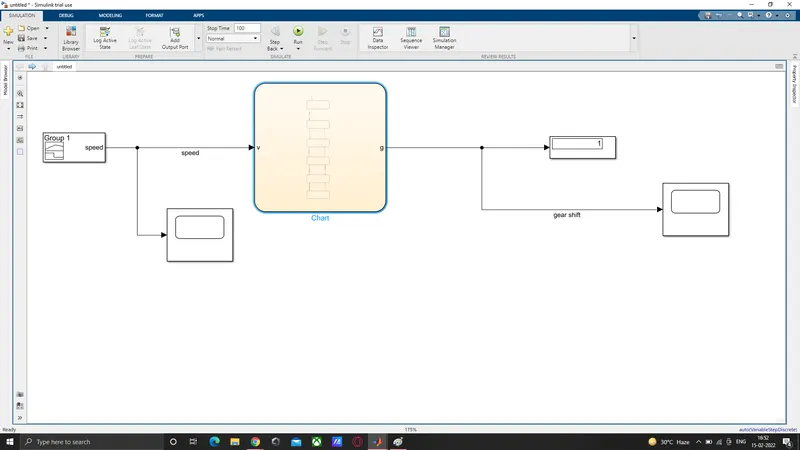
the picture shows the block reprsentation of gear shift
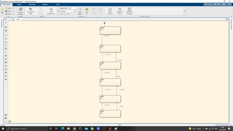
chart which shows the transition states of gear shift
explaination-
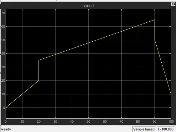
1-speed is varied and built using signal builder as shown in the below speed chart.
2-the input taken by the chart with respect to speed is taken in.
3-the gear shift according to the condition given to the block .
4-each condition is set according to the gear and speed.
5-as the speed increases the higher gear is applied and vice versa.
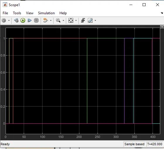
6-the time for which gear is shifted according to the speed is shown in the bellow gear shift chart.
speed chart
gear shift chart
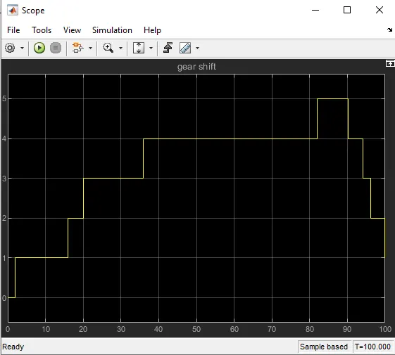
as speed increases higher gear is applied , also when the speed decreases the lower gear is applied