Week - 4
1.Implement control logic of a “washing machine” using Stateflow:
Model:
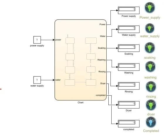
- The blocks used in this model is constant block,Chart block,Display block and Lamp.
- we use two constant block as inputs one is for power supply and other one is for water supply.
- we use seven Display blocks to show the value of the outputs same as well we use seven Lamp(LED) to indicate ON adn OFF of the system.
- In Lamp Green light indicate's the system gets Activated,Red light indicate's system gets Deactivated.
- The Stop time is given as 500 sec.
Condition:
- Soaking time should be 200s followed by Washing time of 100s.
- Then rinsing happens for next 20s & dryer runs for 50s.
As per the given condition the chart is created.
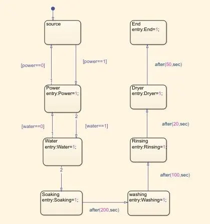
- Stateflow is the simulink tool to implement the state machine.
- Inside the Chart we use state machine there are source state, Power state, Water state, Soaking state, washing state,Rinsing state, Drying state and End state.
- In between source state and Power state we use two conditions to the given inputs,there are [power==1][power==0].
- In between power state and Water state we use two conditions to the given inputs,there are [water==1][water==0].
- If condition is 1 the system is Activeted to the process,If condition is 0 then the system is Deactiveted and the process is stoped.
- Then the rest of the state's are Activeted when the condition is 1 for Water state.
- Power state and Water state are the inputs,rest states are outputs set inside the chart by "Symbles pane"
Output:
- If the power supply is available, the system gets activated.
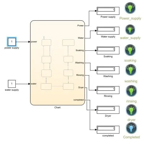
Heare the both power supply and water supply inputs is given as value=1,so the system get activeted.
- If the Water supply is not available, stop the process & indicate through LED,the result is shown below:
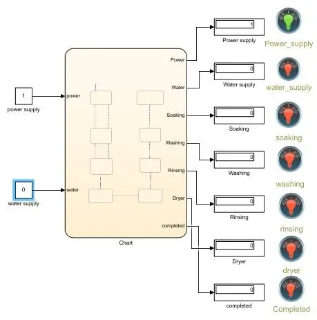
Heare the Water supply input is given as value=0 the lamp(LED) indicate"s Red color, so without Water supply the process is stoped only the power supply is in ON.
- After all the processes have completed turn on the finished LED,the result is shown below.
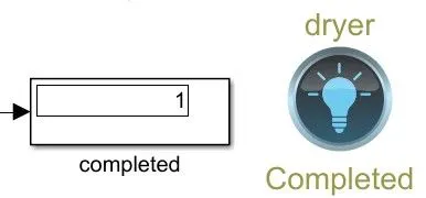
After all the processes have completed The lamp is turned on as Blue color.
2.Make a Simulink chart for the “Gear shift” logic as per below conditions:
Speed Range(kmph) Gear
0 to 15 1
16 to 25 2
26 to 40 3
41 to 60 4
Above 61 5
Simulink chart for the Gear shift logic:
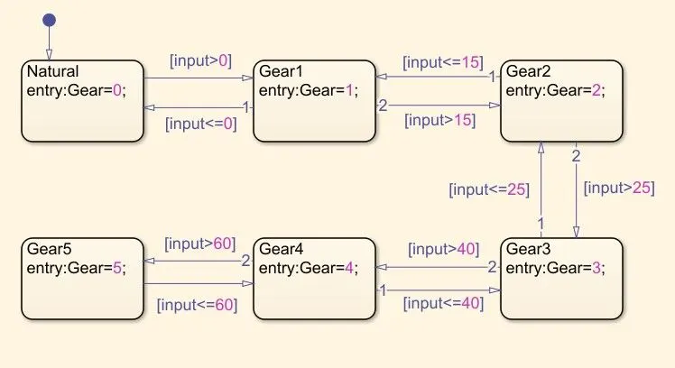
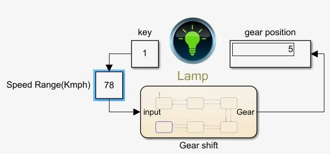
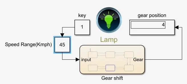
- If The key=0,then the power is OFF,lamp indicates Red color and Gear Shift mechanism will not be active.
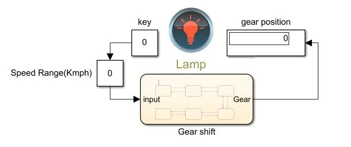
- If the key=1,then the power is ON,lamp indicates Green color and Gear Shift mechanism will active.
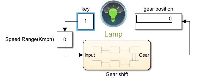
- In this model we use constant block,Slider Gain block,chart block ,display block and Lamp.
Output:
Give speed input while the simulation is running & display the gear number?
Case 1:
- The stop time is given as "inf"
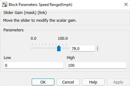
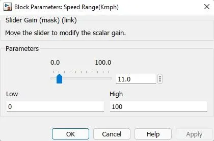
- Slider Gain block [speed Range(Kmph)] is used to vary the speed while running the simuliation.
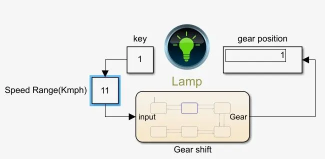
- Start running the model and By varying the Speed as "11 Kmph" to the Slider gain(Parameters),so the gear position is change to "1" and stop the running model.
- For 1st Gear the given condition of Speed Range(Kmph) is between "0 Kmph-15 Kmph".
Case 2:
- The stop time is given as "inf"
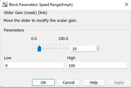
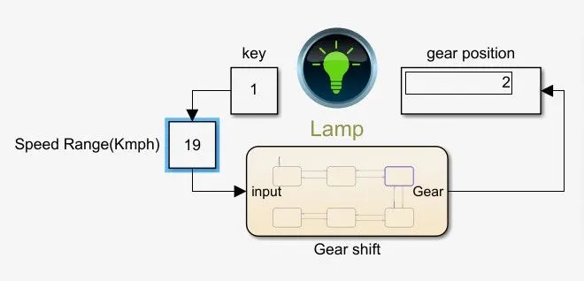
- Slider Gain block [speed Range(Kmph)] is used to vary the speed while running the simuliation.
- Start running the model and By varying the Speed as "19 Kmph" to the Slider gain(Parameters),so the gear position is change to "2" and stop the running model.
- For 2nd Gear the given condition of Speed Range(Kmph) is between "16 Kmph-25 Kmph".
Case 3:
- The stop time is given as "inf"
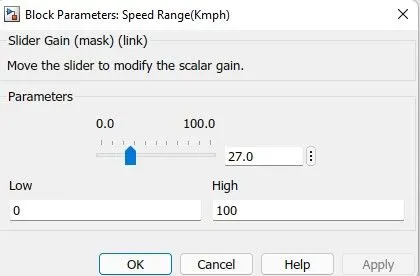
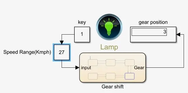
- Slider Gain block [speed Range(Kmph)] is used to vary the speed while running the simuliation.
- Start running the model and By varying the Speed as "27 Kmph" to the Slider gain(Parameters),so the gear position is change to "3" and stop the running model.
- For 3rd Gear the given condition of Speed Range(Kmph) is between "26 Kmph-40 Kmph".
Case 4:
- The stop time is given as "inf"
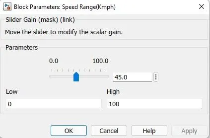
- Slider Gain block [speed Range(Kmph)] is used to vary the speed while running the simuliation.
- Start running the model and By varying the Speed as "45 Kmph" to the Slider gain(Parameters),so the gear position is change to "4" and stop the running model.
- For 4th Gear the given condition of Speed Range(Kmph) is between "41 Kmph-60 Kmph".
Case 5:
- The stop time is given as "inf"
- Slider Gain block [speed Range(Kmph)] is used to vary the speed while running the simuliation.
- Start running the model and By varying the Speed as "78 Kmph" to the Slider gain(Parameters),so the gear position is change to "5" and stop the running model.
- For 5th Gear the given condition of Speed Range(Kmph) is "Above 60".