Week -2
1.Make a Simulink model of Doorbell using solenoid block with the following details:
Objective:
The model to be designed for a situation where the switch is closed for 2 secound and then released to observing the physical movement of the plunger.
Simulink Model:
Working:
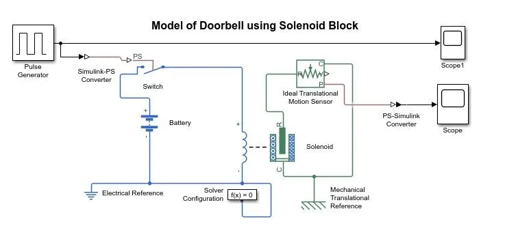
- In above Model there are three color representation,green,blue,Black.
- Green color representaion Machanical system,Blue color representaion Electrical system,Black color repesentaion Simulink system,These three system comes under Physical system.
- The blocks that are used in this model are Battery,Solenoid,Ideal Translational motion Sensor,Machenical transtional reference,Solver configuration,switch,electrical reference,Scope,Pulse generator,simulink-PS convertor and PS-simulink convertor.
- The switch,battery,Electrical reference and Solver configuration is connected to the electrical part of the solenoid.
- The Ideal Translational motion Sensor,Machenical transtional reference is connected to the machenical part of the solenoid.
- From the motion senor the plunger position is found using the scope block.
Input parameters:
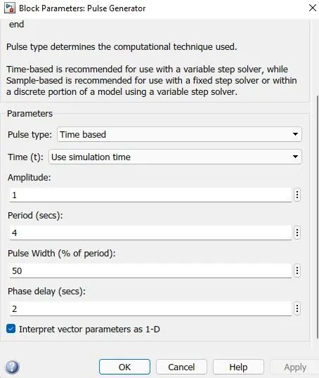
- In pulse generator,the input is given where the switch is closed for 2 seconds and then released.so in the phase delay we have given 2 as the input and in period 4 sec is given and the plunger in the graph between the time plots
Result of scope1:
Result of scope:
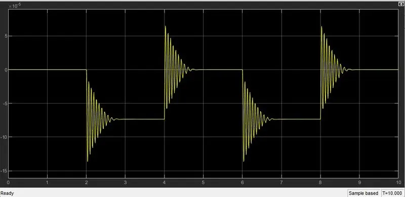
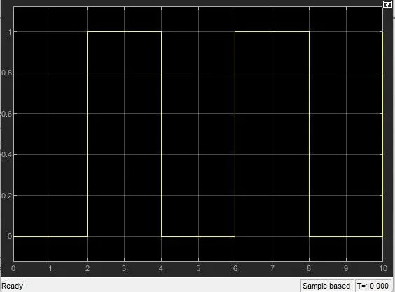
- In the solenoid parameters we have given the Spring constant value of 600 N/m and the Damping value as 0.2 N(m/s) from the default value.so from this value the above result is obtained.
- The graph represents the soundwave that occurs with a time difference of 2 seconds which observe the physical movent of the plunger.
2.Use a thermistor to sense the temperature of a heater & turn on or turn off the fan?
conditions:
Temperature source: 20 °C from 0 to 10 seconds, 27 °C from 10 to 30 seconds, 23 °C from 30 to 50 seconds
Fan conditions: ON if the temperature above 25 °C, OFF otherwise
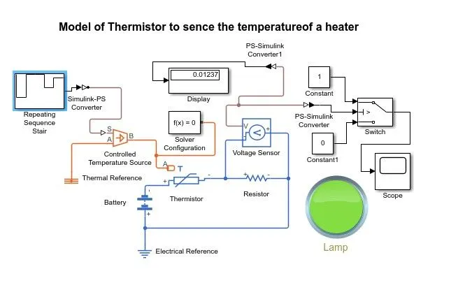
Simulink Model:
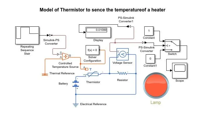
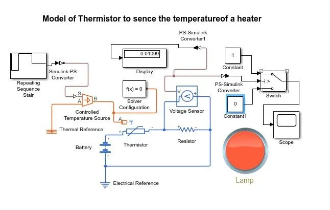
- Blocks used in the model are Repeating Sequence stair,Controlled Temperature source,Thermistor,Resistor,Voltage sensor,Battery,Switch,Lamp,Scope,Display,PS-Simulink convertor,Simulink-PS Convertor,Solver Configuration and we use two reference one is to electrical part and other one in Thermal part.
- A Repeating Sequence stair is given as input to the thermistor throught a controller themperature source.
Repeating Sequence stair parameters:
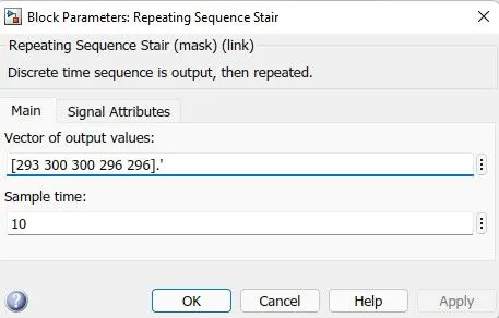
- The conditions of the temperature source is given in above window.the sample time was taken as 10 second and the whole simulation time was taken as 50s.
- Battery and resistor is connected in the termistor in the circuit.
- A voltage sensor was given accross this resistor to measure the voltage change during difference temperature inputs.
- The resistance of the resistor can be set to any value,but it should not be change once the threshold voltage is found.
- The threshold temperature was given as 25 degree celsius or 298.15 k and the corresponding voltage over the resistor was found out ,throught a display connected to the voltage sensor.
- At this time Repeating Sequence stair was given only one valve,i.e,25 degree celsius or 298.15 k.
- The output from the voltage was also given into a switch which is linked to a lamp which displays a different colours based on the logical conditions.
- The lamp color was set to red if the tempertaur was below 298.15k and to green when the temperature is above 298.15k.
Results:
1.Scope result:
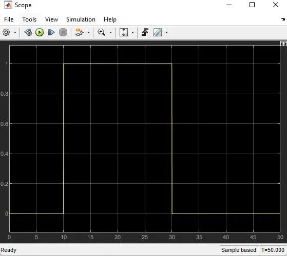
2.When the temperature is above 298.15k or 25 degree celsius:
3.When the temperature is below 298.15k or 25 degree celsius: