Week - 4
control logic of a “washing machine” using Stateflow
objective: using chart block construct the state flow of washing machine by control logic.
simulink model and explanation:
How does washing machine work?
soo we know that washine machine is electric mechanical machine which needs electricity.
in washine machine first we need to give power supply.after that we need to fill the machine with water add detergent.
the machine will soak the clothes and next stop will be washing,after washing machine will rinse the clothes and throw out water ,the last step will be drying.
below are the conditions given for us to build state flow using control logic:
- If the power supply is available, the system gets activated
- If the Water supply is not available, stop the process & indicate through LED
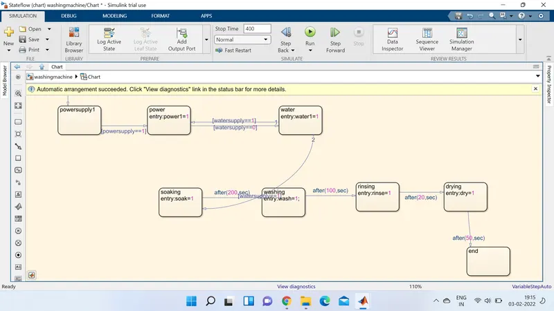
- Soaking time should be 200s followed by Washing time of 100s.
Then rinsing happens for next 20s & dryer runs for 50s
the below image shows the model for above conditions on simulink using stateflow 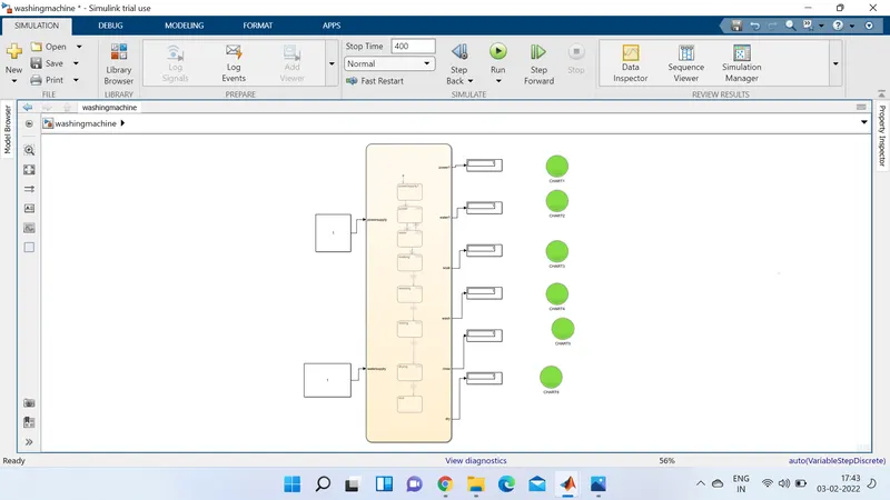
the above picture is made of three blocks manily
1.constant
2.chart
this block is used to design the state flow of system by using this we made the above model soo the chart block is shown below.
3.display block
If the power supply is available, the system gets activated
If the Water supply is not available, stop the process & indicate through LED
in the picture given below we can see that when powesupply is 1 the system gets activated and when power supply is 0 led shows red.
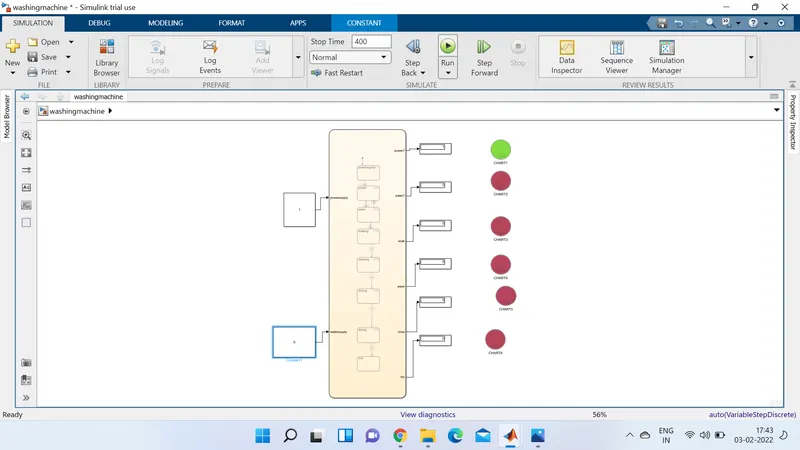
two conditions above is verified by the image.even though the power supply is active because of no water supply system stopped and we can see as in the lamp showing red.
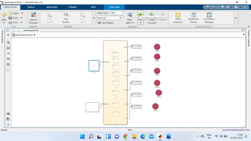
for the remaing conditions we can verify from model picture.
“Gear shift” logic simulink chart
objective:
Make a Simulink chart for the “Gear shift” logic as per below conditions:
Speed Range(kmph) Gear
0 to 15 1
16 to 25 2
26 to 40 3
41 to 60 4
Above 61 5
Give speed input while the simulation is running & display the gear number.
simulink chart and model:
by using chart block we makeb the below chart state flow for above gear shift logic and display speeds in the simulink model as well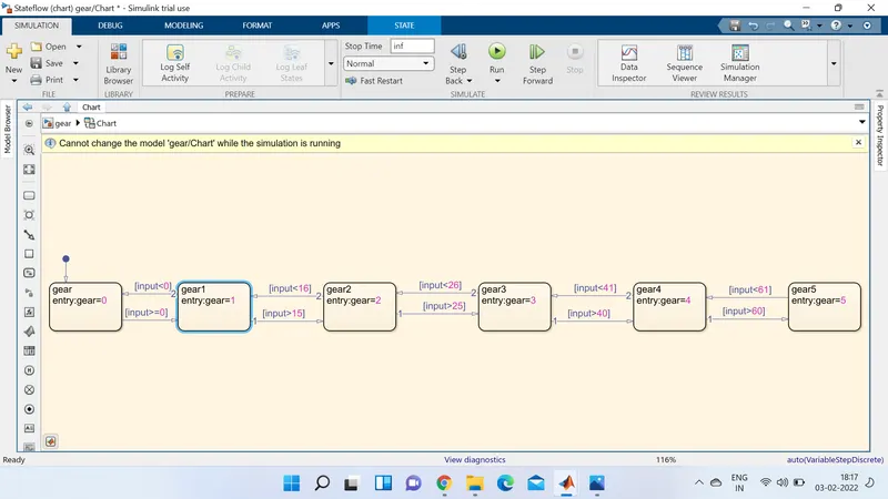
in above chart we used input and gear as ports and gave the above conditions given in question the simulink with chart shown below.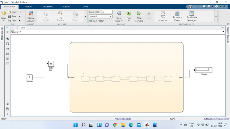
the results for above conitions are given below and we dispaly the gear number according to conditions in below pictures.
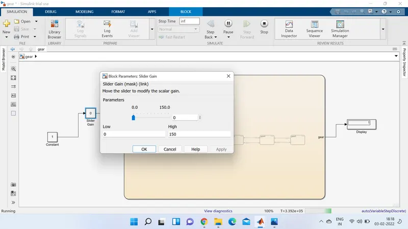
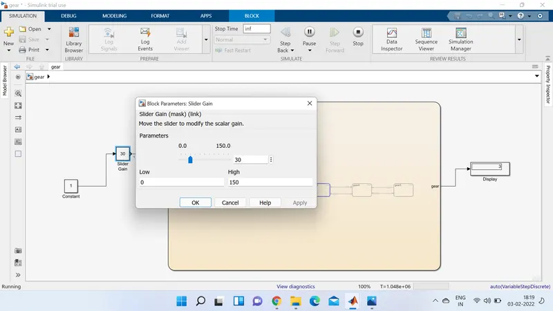
by using slider gain block we vary the speeds while running the simulation by giving inf time as running time.