Week - 4
Aim :
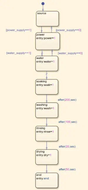
Implement control logic of a “washing machine” using Stateflow as per given sequence:
- If the power supply is available, the system gets activated
- If the Water supply is not available, stop the process & indicate through LED
- Soaking time should be 200s followed by Washing time of 100s.
- Then rinsing happens for next 20s & dryer runs for 50s
A washing machine is spinning at 800 to 1600 rpm helps soap and dirt with it to leave the surface of the cloth via centrifugal force and into the oulet pipes hence utilise centrifugation to both clean and partially dry the cloth loaded in the washing machine.
The process are electrically controlled such as follows
Drum, valve pump, motor and heating elements etc....
When the valve opens the dirty water drains out of the drum
The valve lets clean water in again in to the drum. & in this 4 process were
1) Soaking - Used to dip cloths in detergent water to remove dirt from the clothes - the soak function is programmed in the panel board itself with in the programmable content as per the requirements setting of program can be selected.
The soak function is available with timer at 42 minutes of washing bifercated as 27 minutes of soaking and the 15 minutes will wash the cloth.
2) Washing - During the wash cycle the platic agiator turns around,, rotating or moving the clothes in and around through water
When the water is finished the pump drains the water from the outer drum. as per the programme cycle. eg 15 mts and according to the set up of the programmed.
3) Rinsing - The dirty soap water is drained and the fresh water will be in with the help of valve lets clean water in again in to the drum, again the clothes will be re washed with the fresh water then after comes SPIN.
Spin - In this process - all the water will be drained completely, then the clothes will spun as per the rpm set up in the program due to centrifugal force, the excess water in the drum will also get drained during the spun process itself, the water will be stored in the reservoir, once the programmed time is finished, the valve lets out the soap water through the drained pipe.
4) Dryer- The warm dry air is pushed through wet washing to extract moisture then cooling, then again humid air in a heat exchanger to condense the moisture, which is collected in a tank or pumped down to drain from the tank.
The air is re heated and ciruclated to the repeats the process.
State - Flow
Systematic solution of a problem is possible with sequential order , the relizable finite process step set is to be followed.
The step set is called as Algorithm - which is most important part of the programming lanugages.
Algorithm - Using simulink stateflow
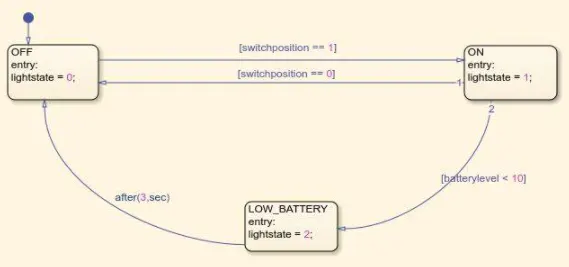
Control logic of washing machine - Which will check the grease and the dirt , the amount of soap detergent and water to add and the directon of the spin and so on.
The machine re balances washing load to ensure correct spinning else, it will reduces the speed and then the imbalance will be deducted and also there will not be an balance distribution of washing will occur, then the load reduces the spinning noise.
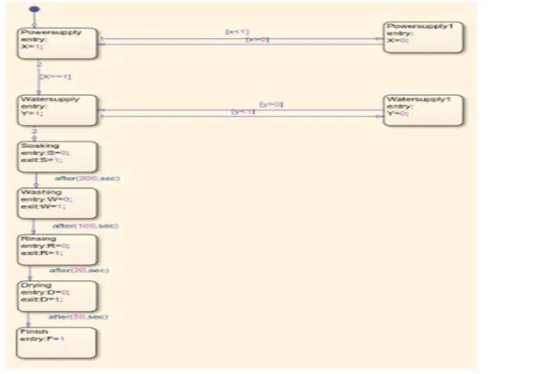
We can see from the set up that the command move from the first block to the second one if the switch posistion is 1, when is in ON Position.
When the switch is on the command will exit showing the value = 1 in the display and the lamp.
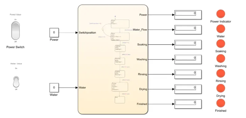
In order to move from the water the soaking stage and the water is turned on else it will not move on the second stage and the process will be stopped.
When Power = 0 & the water is 0, the above image indicates will be in the same condition.
& in the continuous process
When Power = 1 & the water is 0, the below image indicates will be in condition.
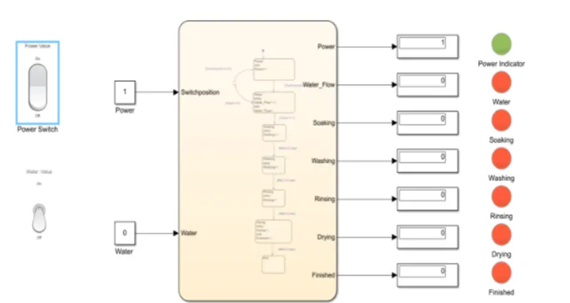
when Power = 1 & the water = 1, the below image indicates will be in condition at time 200 sec.
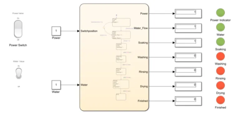
Saoking will take place for 200 sec, after the soaking then stage move for washing.
when Power = 1 & the water = 1, the below image indicates will be in condition at time 250 sec.
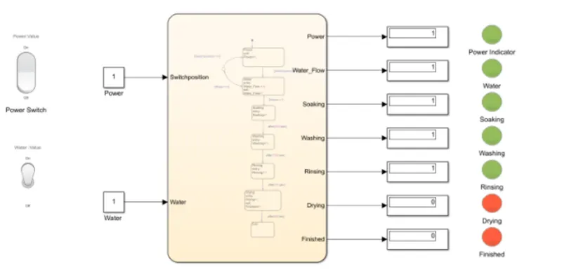
After washing the rinsing will take place for 20 sec , after rinsing the next then stage move for next process.
when Power = 1 & the water = 1, when at time 350 sec.
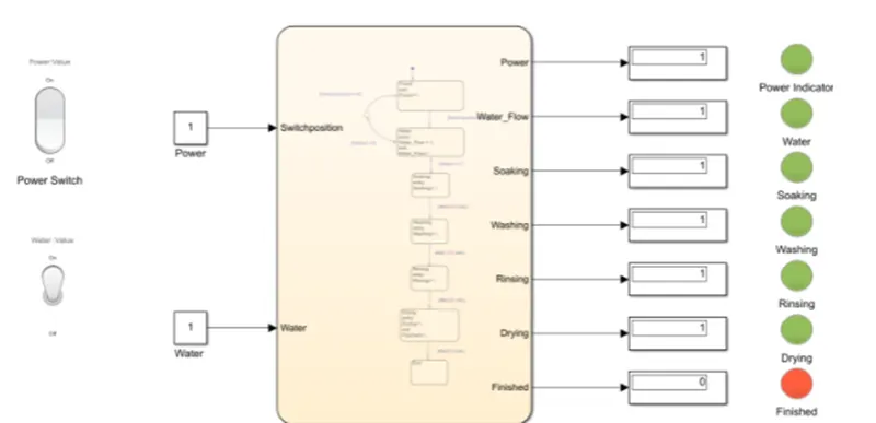
then the whole process will be completed at 400 seconds, the complete process is over and the green light turn on
the process takes place at every 400 seconds.'
Make a Simulink chart for the “Gear shift” logic as per below conditions:
Aim : To make Simulink chart for the “Gear shift” logic as per below conditions
Speed Range(kmph) Gear
0 to 15 1
16 to 25 2
26 to 40 3
41 to 60 4
Above 61 5
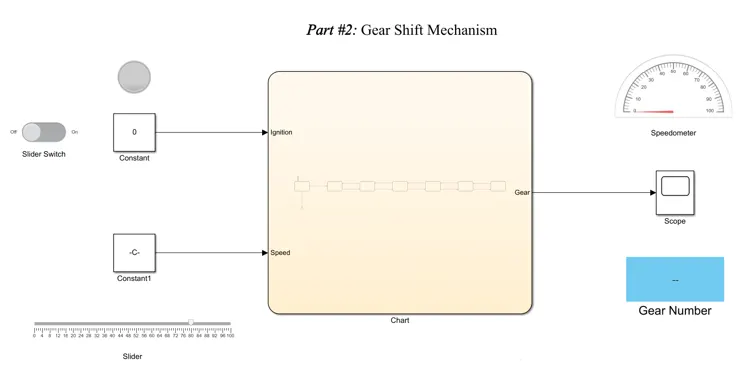
Model of the “Gear shift " in Simulink
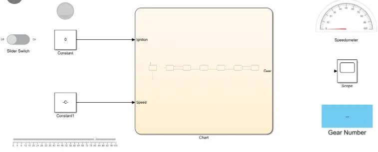
State Flow
Explanation :
1. To create a simulink model of gear shift create a stateflow and start with the power block which is connected to the breakpoint and a junction with power = 0
Condition and connected to the speed block state power = 1 ,
so when the speed is above 1, then the process will start flowing to gears
2. Mentioned to speed and the conditions above gears , the speed greater than Zero, the gear shift should start the cycle of changing the gear (Next gear -- Next Gear )
3. First gear mentioned breaking point is 16 then respectively changing till 61
4. From 5th Gear to 1st Gear the arrow indicates up sd arrow (Breaking point)
the gear is decreased till Zero , we can shift the gear not only increasing and even decreasing also.
5. Top gear is mentioned as state, if the speed is increased by above 80 there is an indication the lamp shows over speed in our simulink block
6. After the chart ready we can see input power and the speed , the output gears and top speed
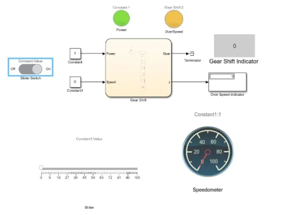
7.By connecting the two constants the power and the speed , when the switch is on, the power will be indicated from the lampwhich will be green in color.
Speed is connected with slider which requires manually increasing the speed.
8. From the output gear connected with terminator so that it stops the data flow and to view the gear shift, it has connected to shift indicator.
The top speed is connected to display
The display is connected to a lamp, which shows the speed and indicates the over speed , so that the lamp indicates the over speed.
9.Then finally slider connected to the speedometer to view the speed in the speedometer.
Result.
Power Off
Power ON
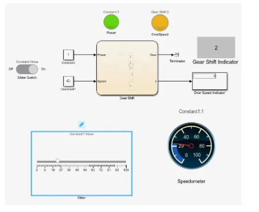
Power ON speed at 20 KM
Power ON speed at 40 KM
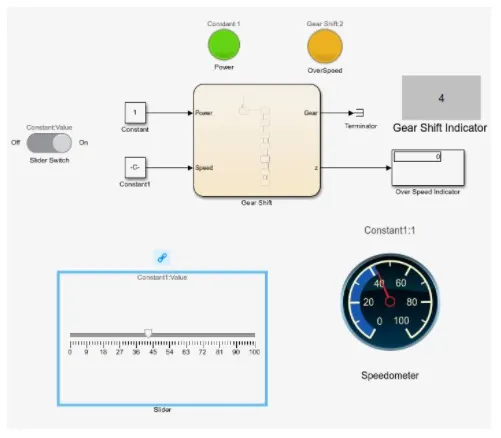
Power ON speed at 60 KM
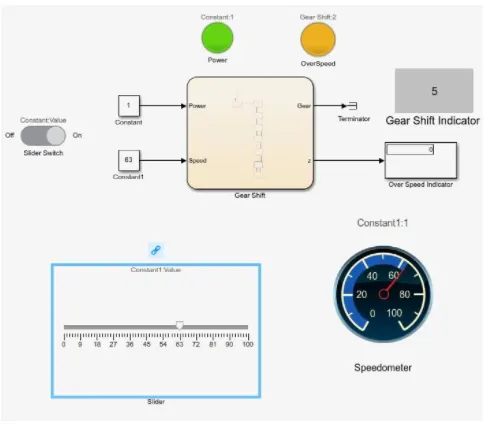
Power ON speed at 80 KM
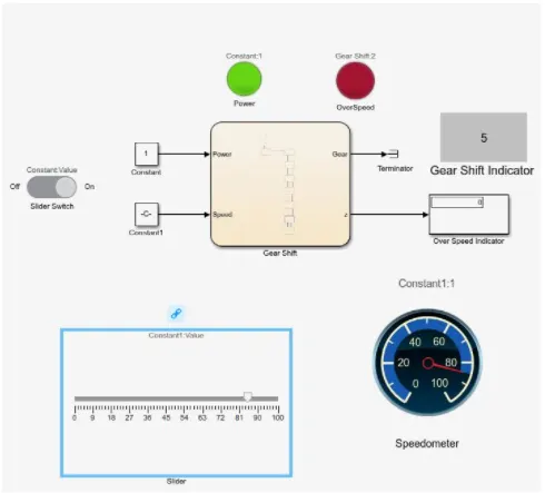
Result : Speed input while the simulation is running & display the gear number shown with details.
The over speed indicator also present
Complete Poke Yoke system is followed,whenver the speed increases the indicator of green light is fixed.