Week - 4
1.Implement control logic of a “washing machine” using Stateflow as per given sequence:
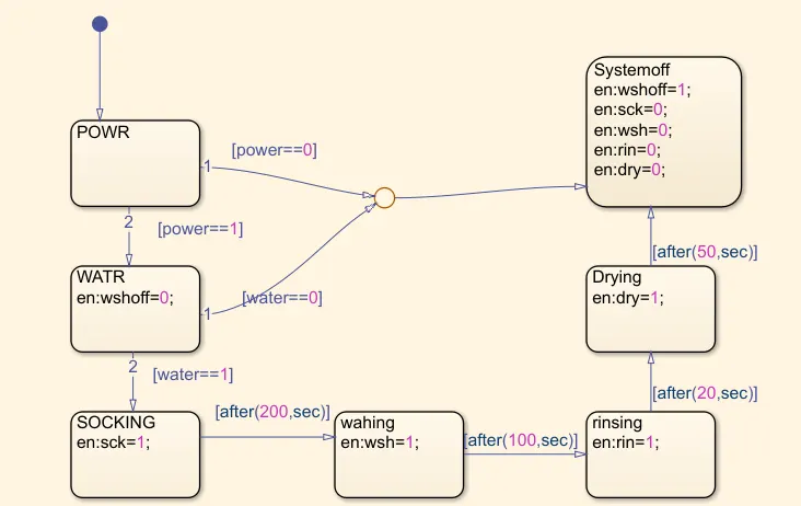
- If the power supply is available, the system gets activated
- If the Water supply is not available, stop the process & indicate through LED
- Soaking time should be 200s followed by Washing time of 100s.
- Then rinsing happens for next 20s & dryer runs for 50s
- After all the processes have completed turn on the finished LED
Simulink model:
Construction:
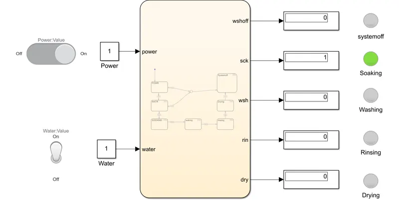
Chart is created to perform thedesired task for each time period.Slider switch and toggle switch is used to on and off the power and water system. Switch is connected to constant which are connected to chart as input. Chart output value is get through separate display. Each display is connected to lamp block to represent the ON and OFF of the operation.
Working:
When the power and water switch is on, the machine is run for given time period.For the respective time the soaking, washing, rinsing, drying process takes place. Once all the process got over System will get to off position by displaying red light. If the power and water supply get stoped system will get to OFF position.
Output:
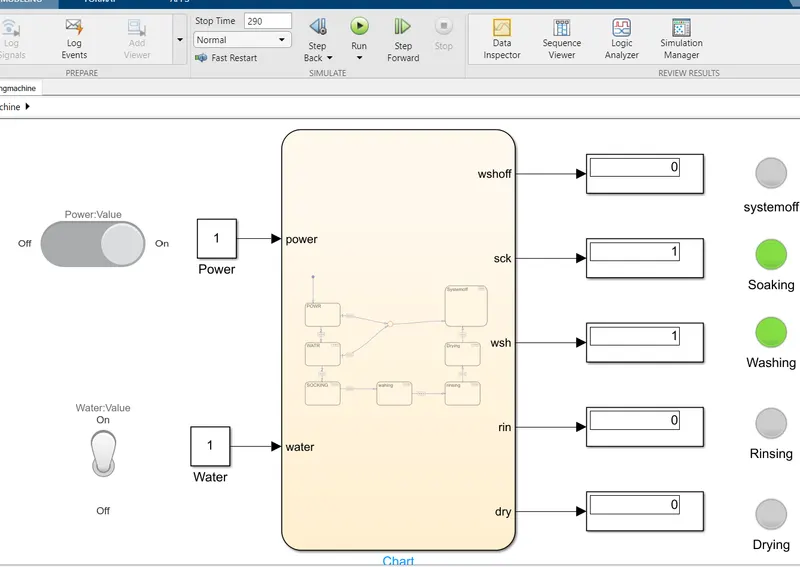
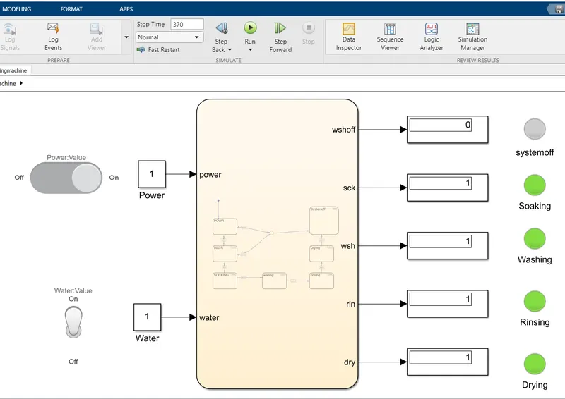
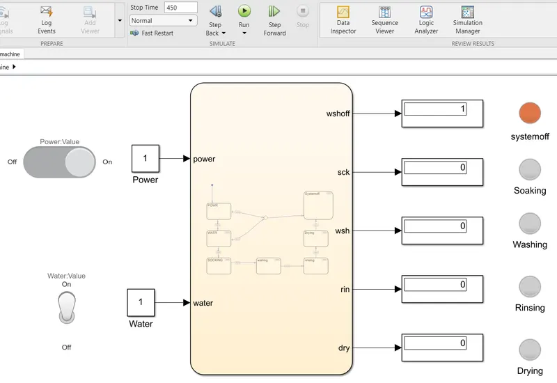
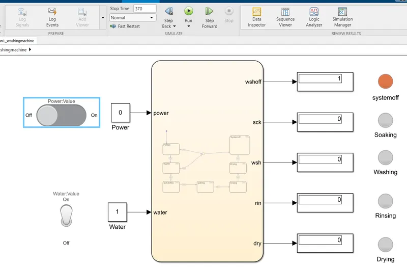
2. Question:Make a Simulink chart for the “Gear shift” logic as per below conditions:
Speed Range(kmph) Gear
0 to 15 1
16 to 25 2
26 to 40 3
41 to 60 4
Above 61 5
Simulink Model:
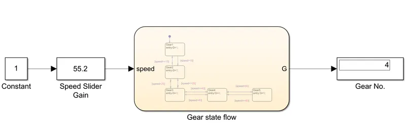
Construction:
Create the stateflow for gear shift in chart block for Add the required state and transition line from tab. Mention the speed values as per the Question in transition lines. Enter the G values in each state to get desired values. For Speed input add slider gain block to vary the input while running the simulink model. Connect the display block to view the Gear no.
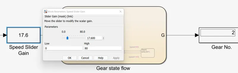
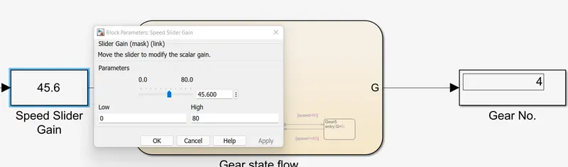
Working: While changing the speed value through slider gain, desired value is given to chart for where it get into the state flow and give the respective G value. the G(Gear No.) value is displayed in Display block.
Output: