Simulink Stateflow models for washing machine and manual transmission.
- Aim : Simulink models for the control logic of different states of a washing machine and manual transmission using the Stateflow in the simulink environment.
- Objective & Workflow : We will be creating two different models for making the control logic for washing machine and manual transmission using stateflow.
- In the washing machine model, we have different states of washing which are soaking, washing, rinsing etc. with constantly checking for power and water supply. If one of the supplies gets disconnected then the system should get deactivated.
- The different states of the washing machine will be changed based on the time delay between each state. We use the lamp block to glow when each state being executed, also we use the scope block to see the transition between states with time.
- In the manual transmission model, we have different states representing different gears which should be changed based on the vehicle speed. We will give speed as the input to the stateflow chart using the slider gain block and display the output in the scope.
- The output from the stateflow chart will be the gear engaged for the current speed. The states representing the gear will change according to the condition of the vehicle speed.
- Simulink Models :
- Washing Machine Model :
- Explanation :
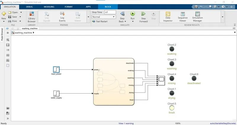
- According to the model requirements we define these different states for complete washing, soaking, washing, rinsing, drying. We assign different time span for which these processes should be done for complete washing as soaking being 200 seconds, washing being 100 seconds, rinsing being 20 seconds and drying being 50 seconds.
- We need to check for power and water supply constantly and if any of them cuts off then the system should go into the deactivated state. After all the processes being done the finish lamp should glow.
- We are using the step block to give as the power and water input and taking the output using the scope block to get the state activation with time. The lamp block are connected with each output state which will glow till that state is activated means when each process of washing will be in action the lamp representing that state will remain on and gets off after its get completed.
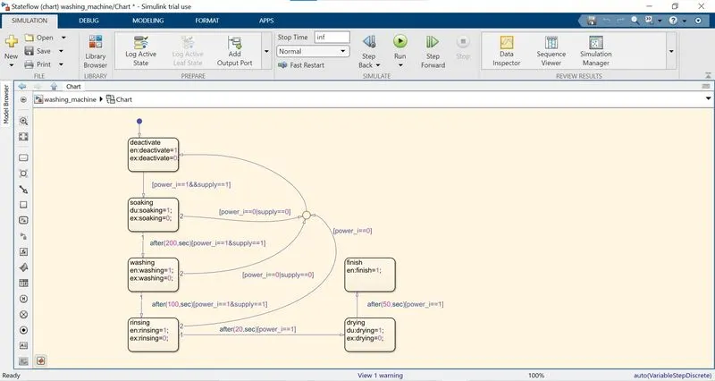
- The stateflow chart above shows the different states and transition event, conditions. The first state we created is the deactivate state. We are taking that at first the system is deactivated then we feed in the power and water supply after which washing processes should start.
- So the condition we put for the transition is to check that both the inputs are equal to 1 or not. We use the AND operator to make sure that both the condition must be true for the tansition to next state.
- The actions we define for this state is while entering and exiting the state. For entering the state the deactivate output get logic on/1 and for exiting the deactivate output get the logic off/0. Basically we are making the state's output on/1 during that state is active.
- After we get both the inputs the soaking state is get activated. In this state also the actions are framed in the same way so that till this state is active, the soaking output will be on/1 and after it get transitioned the output will be off/0.
- We need that the soaking should be done for 200 sec. and both the inputs are still feeded to move to the next process of washing. So what we do is create an event using after for 200 seconds and use condition to check that if both the inputs are still feeded. If the condition is true then after 200 seconds the transition 1 will take place and the washing state get activated.
- Remember we need to keep a check if both the inputs are feeded but if any of the inputs gets cuts off then the system should get deactivated, for that we create another transition condition from the soaking state to the deactivate state. The transition condition is that if any one of the inputs get off, so we the OR operator to do so.
- As we will be checking the inputs at all stages so we use the junction to get the transition from each state to the deactivate state with same or a bit different condition.
- Now the washing state is active and this process should be done for 100 seconds. So to do so we use the after event of 100 seconds and keep checking the inputs to go the next process of rinsing. The output as defined above will remain on/1 till its state remains active.
- Now the rinsing state gets activated and we need it to be done for 20 seconds, so we do the same as above add an event using after and keep checking the inputs.
- After 20 seconds the drying state gets activated which we want to run for 50 seconds, so using the after event of 50 seconds we get the output of on/1 from the drying variable.
- As all the processes of washing has been completed we want to reach a finished state and also a lamp showing that the washing is completed. So after the drying state the finish state is created whose action is for entering the state the finish output will be set to on/1.
- Results :
- The simulation time is set to infinity means we start and stop the simulation by ourselves, this is because if we give a simulation time then the fix time step is causing a delay in the transition from one state to another.
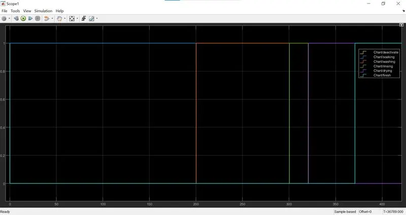
- As we can see the states are running for the required time and after the washing has been completed the finish state gets activated and remains on after that.
- We also check what if the water supply gets cut off in between and the deactivate state gets activated. So to do so we use the pulse generator block named as water supply1, also we can use the same to so for the input power.
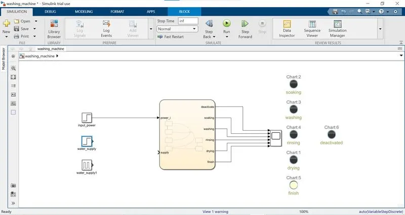
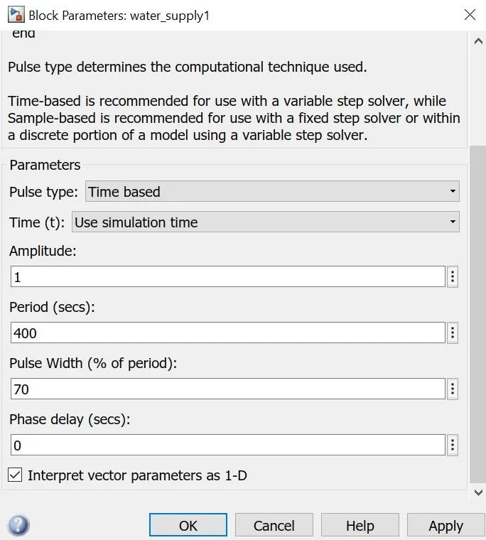
- In the pulse generator block we assign the parameters as follows. The PWM is set to 70% with the time period of 400 sec.
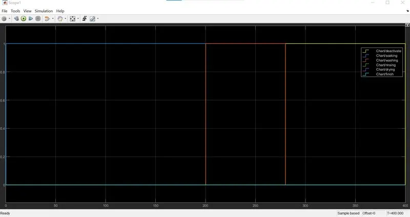
- According to the control logic we have set as if the inputs get cuts off the system should transit to deactivate state. In the result we can see that when the water supply get turned off the deactivate state gets activated.
- Manual Transmission Model :
- Explanation :
- In this model we have to create the control logic for changing gear according to the speed of the vehicle. The input will be the speed and in the output we will get the gear number accordingly.
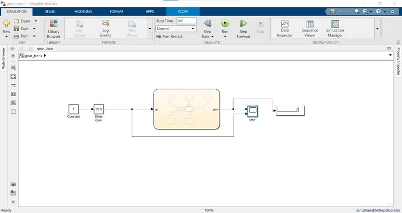
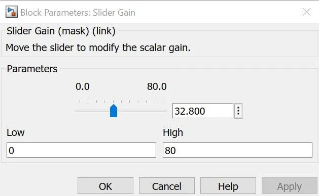
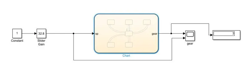
- We use the slider gain block to change the speed input to the stateflow chart. We can change the speed input while the simulation is running using the slider gain block. The slider gain will change the gain and apply it to its input signal. We give a constant one input to the slider gain so that we can directly change the output from the slider gain block with a margin of 1 unit.
- The output is displayed using both scope and display, in the scope we show the gear number with respect to input speed.
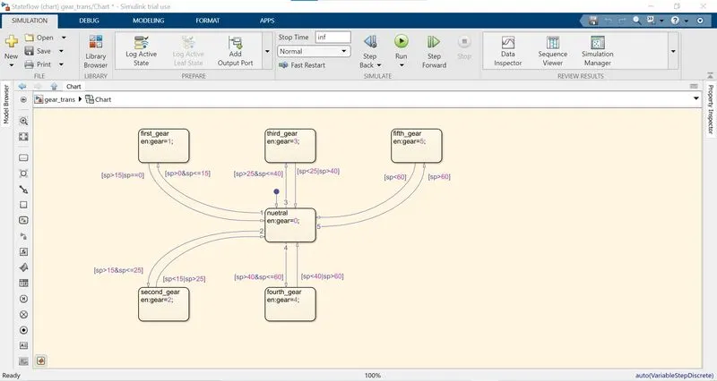
- The different states in the stateflow chart represent the gear being from neutral to fifth. The transition condition we take is the input speed. According to our requirement the we have assigned a specific range for each gear and it is as for first gear 0 to 15, for second gear 16 to 25, for third gear 26 to 40, for fourth gear 41 to 60 and for fifth gear above 61.
- So we start from the nuetral state and has created a logic such that from neutral state we can make transition to any gear state according to the input speed but from each gear state we can also make transition back to nuetral only.
- For example the vehicle starts moving and from the neutral state we transit to first gear state and as the speed increases or come to hault again there will be a transition back to neutral state and make a transition to the another gear state according to the speed.
- We have created speed range conditions for each gear state from the neutral state so that it can transit to any gear according to the speed. And whenever the speed goes out of the range for a specific gear it get transit back to neutral and then again back to another gear state.
- So the neutral state is connected to all other states and has an entry action of making the output gear to 0 stating the nuetral position.
- We have created a speed range condition using the logical operators like <=,> etc.. So for the first gear state we make a transition condition that speed must be greater than 0 and less than equal to 15. In it we use the AND operator to make sure that both the conditions must be true.
- If the speed goes back to 0 or get more than 15 then it must go back to neutral, from there to another state according to the speed input. We use OR operator to make sure that if any one of the condition gets true transition takes place.
- Now while making the speed range condition for second gear we need to understand that for speed of 15 the gear should be first but as soon as the speed increases from 15 and below 16 there must be a gear engaged or how the vehicle is incrasing the speed without any gear engaged. So for second gear state the transition condition is speed greater than 15 and less than equal to 25.
- Now while making the transition condition back to neutral from the second gear the condition is speed <15 or >25 because as speed even get equal to 15 it should be in first gear and even the speed =25 it should remain in the second gear so the condition is >25.
- The similar condition logic goes for the third and fourth gear. But for the fifth gear it become more simple as the speed goes above 60 there must be a transition to fifth gear state and when it goes below to 60 transition must take place back to neutral.
- Results :
- The simulation time is set to inf so take desired time to change the speed input.
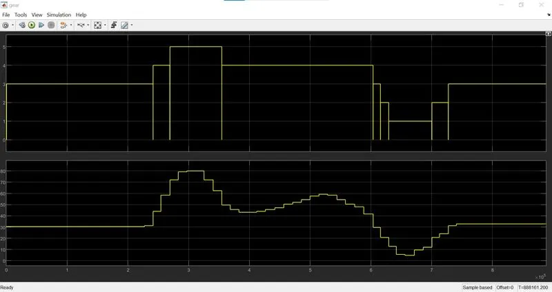
- As we can see that initially speed is 32 so according to that in the output we get that third gear is engaged. As the speed the increases the fourth and then fifth gear get engaged. The transition is taking very fast as soon as the speed goes from one gear range to another the gear changed. The transition time between states depend on the step time for the simulation time.
- Simulink Models Link :
- https://drive.google.com/drive/folders/1PLpXAXsSYKXOjdoY3OxJzF3kKQgANJl-?usp=sharing