Week - 4
1-AIM
Implement control logic of a “washing machine” using Stateflow as per given sequence:
The washing machine – sometimes combined with dryer - is the home appliance with perhaps the longest development history, with commercial models introduced as far back as the mid 1850’s! Today they are required to clean more effectively while consuming less energy, water and detergent, and operate at the lowest possible noise levels while ensuring greater safety.
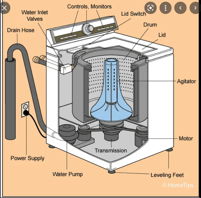
stateflow creates an untitled Simulink model that contains an empty Stateflow chart. The function also opens the Stateflow block library. From this library, you can drag Stateflow blocks into models
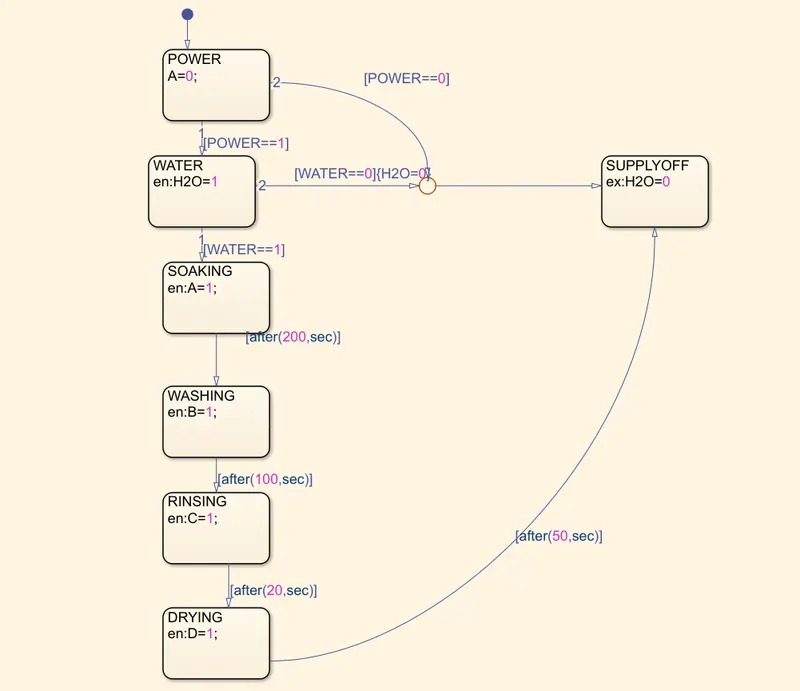
- If the power supply is available, the system gets activated
- If the Water supply is not available, stop the process & indicate through LED
- Soaking time should be 200s followed by Washing time of 100s.
- Then rinsing happens for next 20s & dryer runs for 50s
CONTROL LOGIC -You can use the blocks to perform conditional control flow logic.
Block used in model:-
1-constant-for water and power supply
2-lamp-to indicate the signal
3-slider switch-to turn the machine on and off
4-stateflow-for control logic
5-display-to show output signal
state flow chart
PROCEDURE
1-For power and water supply we have given slider switch for on and off .
2-if power and water is on the signal with given flow logic for 0 and 1.
3-first water then soaking for 200 sec then after soaking washing for 100 sec.
4-rinsing for 20 sec then drying for 50 sec then washing is done each process is denoted by lamp.
when water switch is off then whole washing machine is off
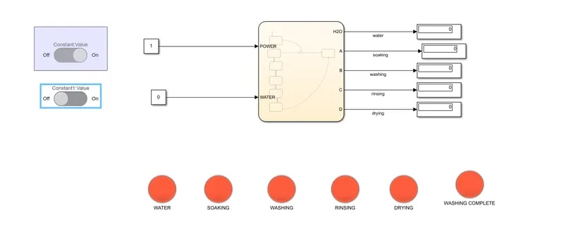
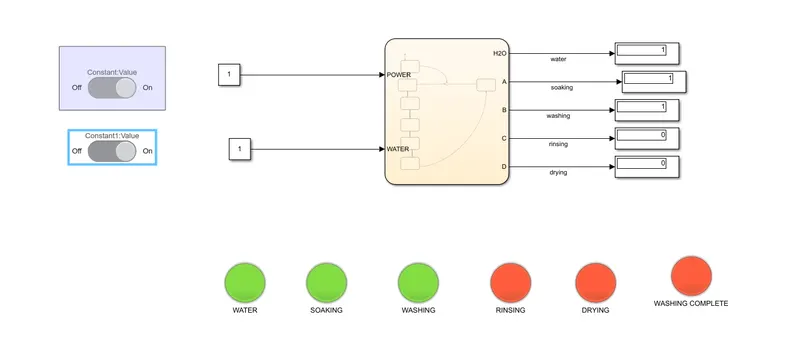
Running the simulink for 230 sec,when supply is on and power is on water and soaking is done rest all are off
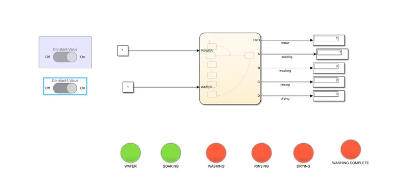
after soaking is done for 200 sec washing is done for 100 sec total 300 sec
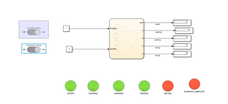
after washing rinsing will happen for 20 sec
then drying for 50 sec then full washing is completed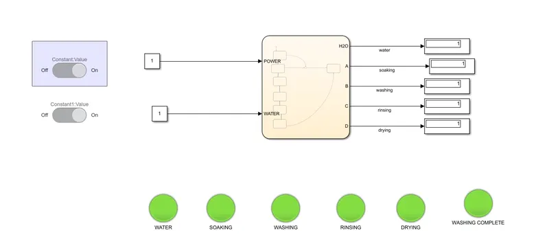
ERROR
i have attached errors and i had removed by correcting in state flow.
2-AIM
Make a Simulink chart for the “Gear shift” logic as per below conditions:
Speed Range(kmph) Gear
0 to 15 1
16 to 25 2
26 to 40 3
41 to 60 4
Above 61 5
TOOL USED
1-Constant
2-Gainslider
3-stateflow
4-display
5-scope
6-gear gauge
Processor
when we drive vehicle below 15 it will run in 1st gear if vehicle will run below 25 the vehicle will run at 2nd gear
when vehicle will drive below 40 the vehicle will drive at 3rd gear and if vehicle will drive below 60 the vehicle will start at 4th gear and if vehicle will drive at speed more then 60 the vehicle will run at 5th gear.here we used 1 and 0 for logic .
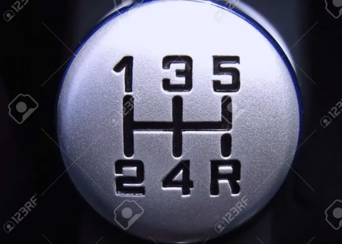
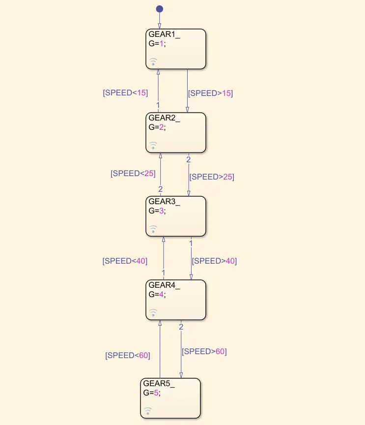
1- When speed is below 15 then run the simulation it will show in 1 gear as output in gauge and display.
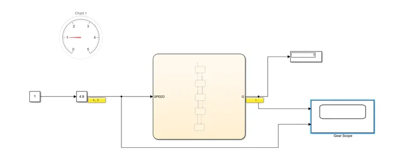
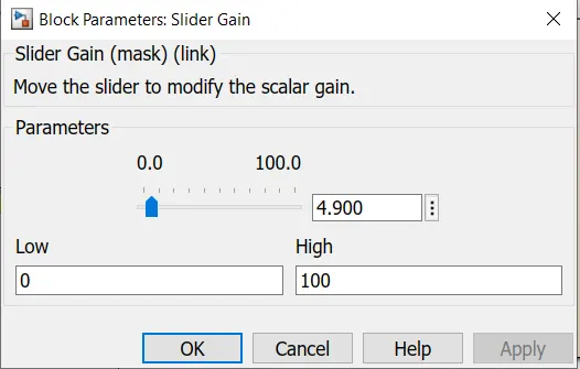
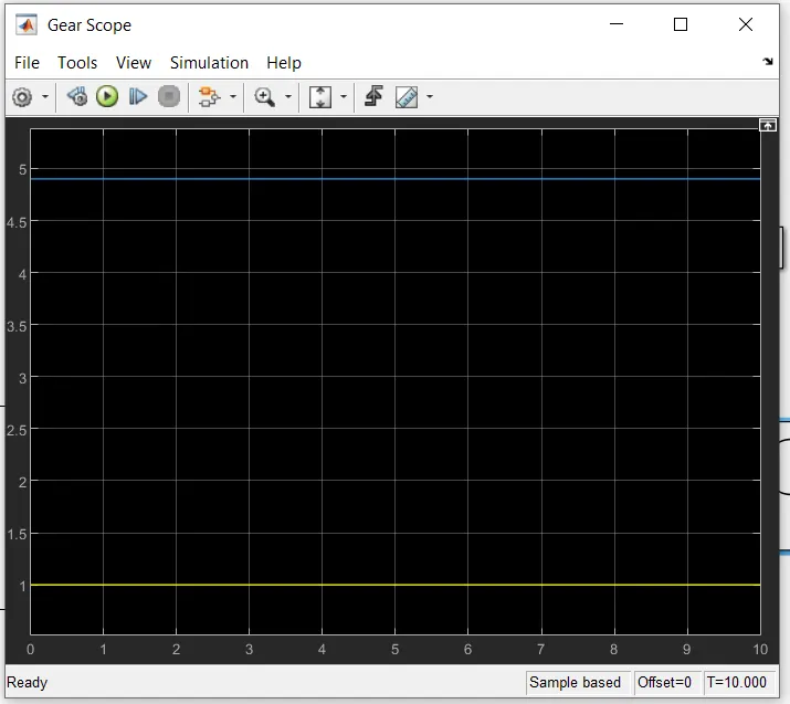
2- when i have speed below above 15 and below and 25 it will show 2nd gear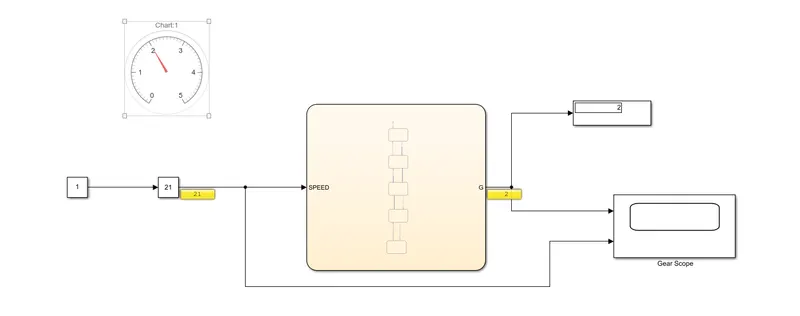
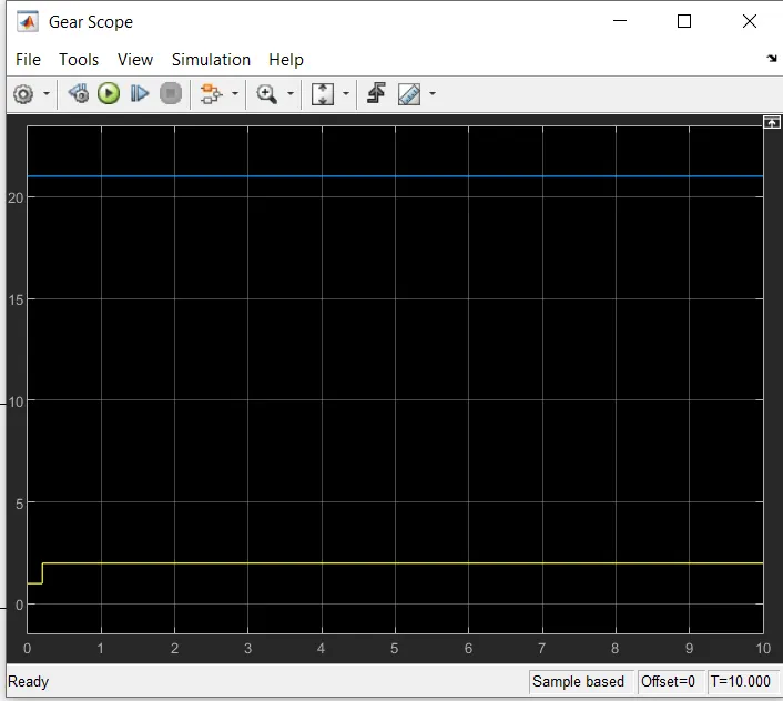
3-when vehicle is running below 40 then vehicle will run at 3rd gear
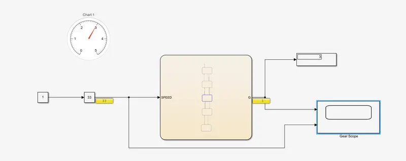
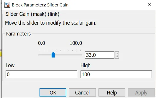
4-when vehicle is running below 60 the vehicle will run at 4th gear
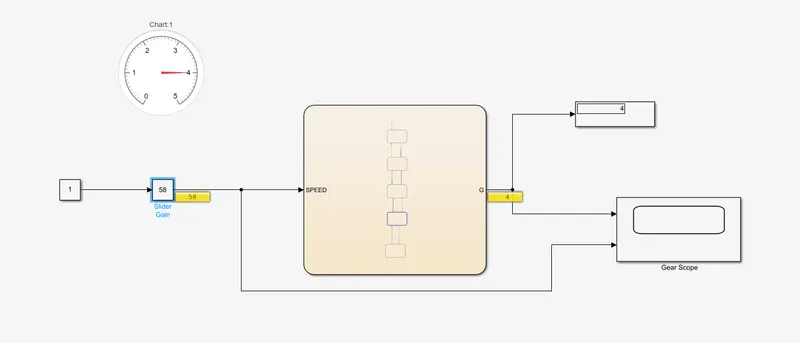
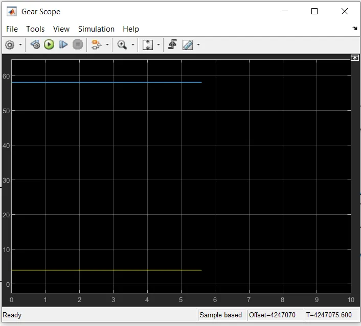
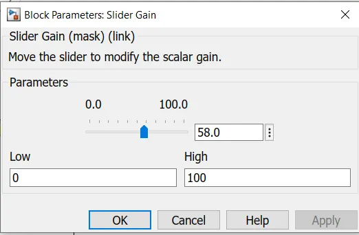
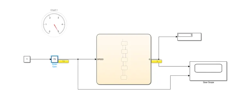
5-when vehicle is running above 60 then vehicle is running at 5th gear.
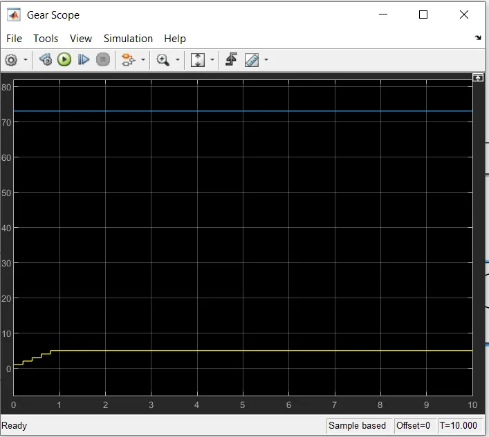
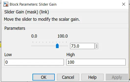
ERROR
image is attached and correction is done.
A gear motor develops torque due to hydraulic pressure acting against the area of one tooth. There are two teeth trying to move the rotor in the proper direction, while one net tooth at the center mesh tries to move it in the opposite direction. In the design of a gear motor, one of the gears is keyed to an output shaft, while the other is simply an idler gear. Pressurized oil is sent to the inlet port of the motor.