Week - 4
Solution:
- Implement control logic of a “washing machine” using Stateflow as per given sequence:
- If the power supply is available, the system gets activated
- If the Water supply is not available, stop the process & indicate through LED
- Soaking time should be 200s followed by Washing time of 100s.
- Then rinsing happens for next 20s & dryer runs for 50s
After all the processes have completed turn on the finished LED
Answer:
Steps:
1. To solve this through statflow in simulink, we need to make us 'Chart' block.
2. Step by step logic is developed inside the chart block as per given conditions.
3. Signals are assigned as 'inputs' or 'outputs' using 'symbols pane' in chart block.
4. Two input 'Rocker Switch' are used to imitate as power on and water supply on.
5. 6 nos of 'Lamps' are used to indicated which state is 'On' phase.
Procedure:
Refer to following screeshot depicting the state flow block diagram created. Lets discuss each state in details.
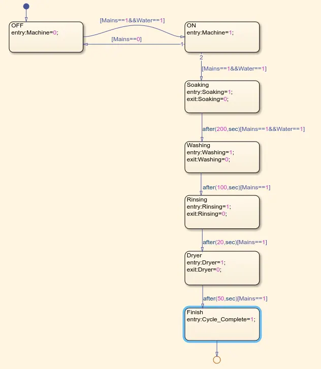
1. The first state, called as 'OFF' is the starting point of our logic development. The parameter 'Machine' is used to denote if our washing machine is On or Off.
2. Second state, called as 'ON' is the state which monitors the inputs given to the state diagram through simulink rocker switches, namely 'mains' and 'water'. This state will be in On phase only if both main power input to the machine and water supply to the machine are on, even if one of these two inputs is not available, machine should not get turned on. Hence we use AND symbol.
3. Next step is to soak the clothes, a state block namely 'Soaking' is created with the parameter name "Soaking', when machine is turned on , our clothes shall start soaking. This is the intention of using this block here.
4.Once clothes are soaked in water, they should be washed. To do so next block namely 'Washing' is used. This state will be on once the pre defined time delay of soaking stat is elapsed, this time delay is a variable as per our choice.
5. Next step is to rinse the clothes, after a thorough wash, water inside the machine is supposed to be gone out of it. of course there is again some time delay given for the washing process to take place properly and our clothes shall not remain underwashed.
6. Once the water is out of the machine, clothes shall be dried off. To do so, we are using next state called as ' Dryer' here the machine will run inot spinning mode at a very high speed. This makes excessive water soaked by clothes to leave out of them and clothes become dry.
7. After clothes are dried, there should be an indication that the cycle has been completed also we can add a buzzer to give an audible signal so the person can understand and come to the washing machine to turn its power off.
Follwoing is Symbols Pane screenshot
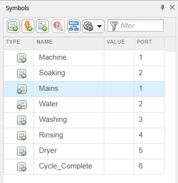
We can assign the parameters as Input or Output depending upon the state or their function. This is achieved by selecting the 'Type' tab in the symbols pane window. Once we do that, there appears a small symbol showing the nature of that particular parameter if its an input or output.
Following is a simulink model screenshot of the system:
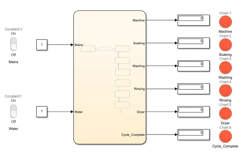
Lets talk in brief about using Lamp and Rocker switch as input of output device. A Lamp can be used to show visually the current status of any of the states or signals.
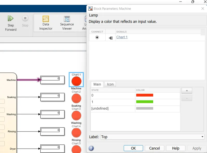
It is possible to add different colors for different states, even we can add multiple states inside the lamp block, also above screenshot shows how to link a particular signal with a specific lamp block.
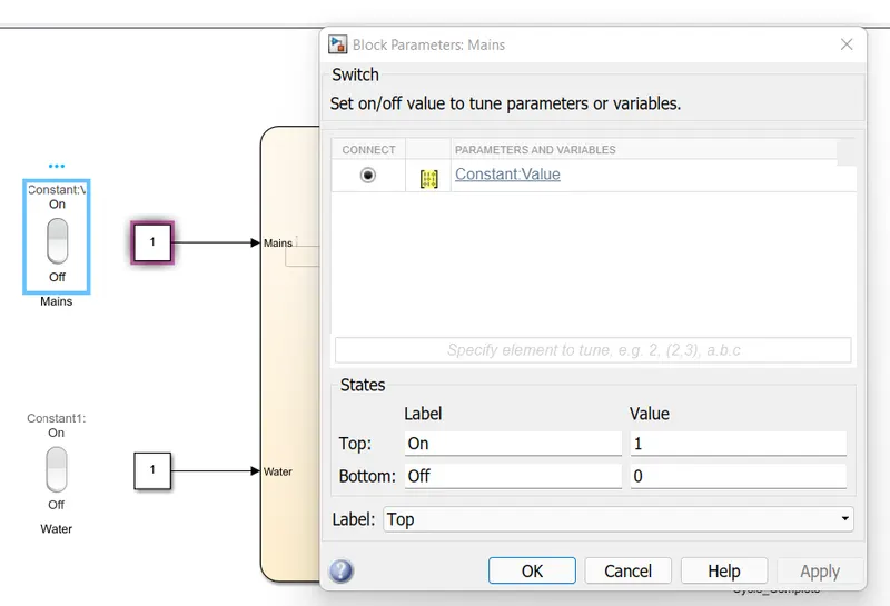
Similarly we can assign states for a rocker switch block as well and the signal can be linked directly.
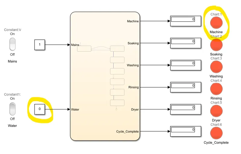
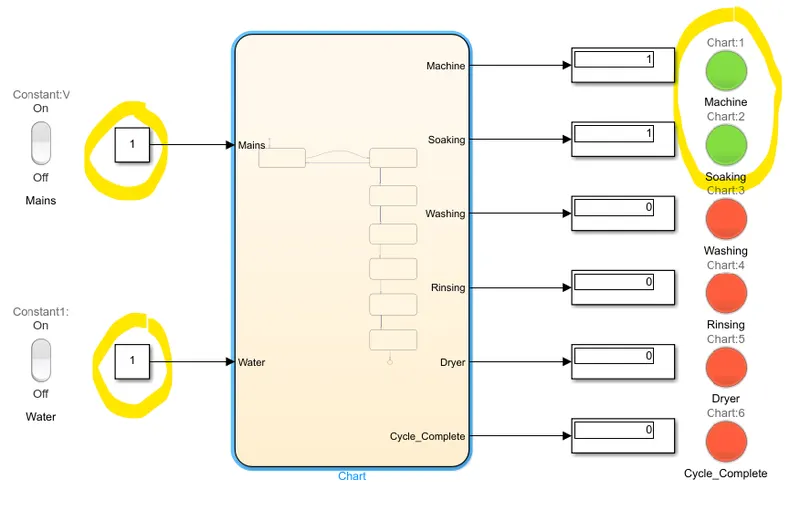
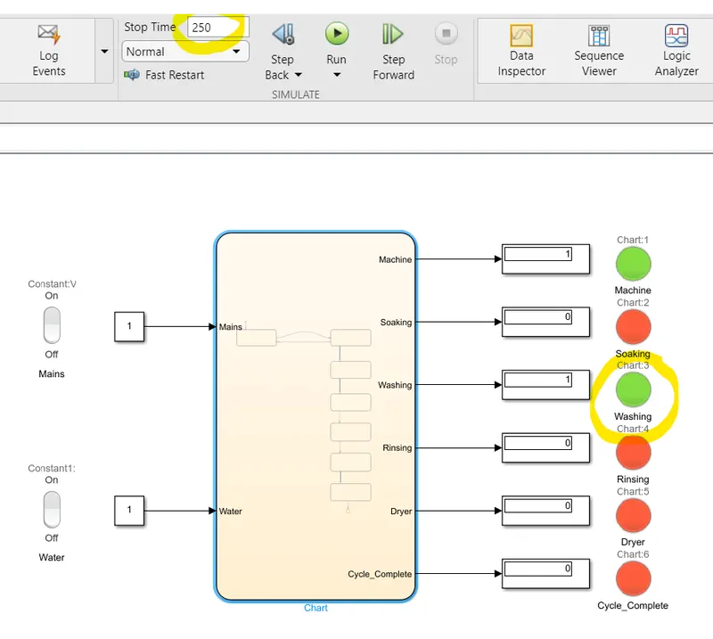
Follwoing screenshots show step by step operation of the model,
1. Machine is off as both or one of the inputs to it is not avalable.
2. Both the inputs are made on so our machine is in On state now and soaking operation is in progress.
3. Soaking operation is finished and now machine is in washing state.
4. Washing operation is finished, time delay has been over and now machine is rinsing out the water.
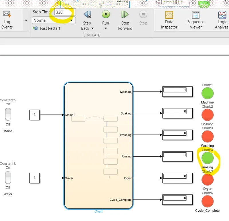
5. Rinsing is done now and machine is running its dryer to dry out the clothes.
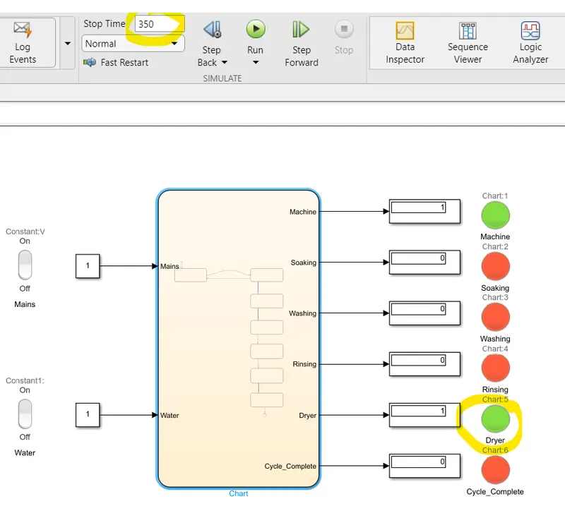
6. Dryer operation is complete and our clothes are washed. so machine is giving out an indication for the same.
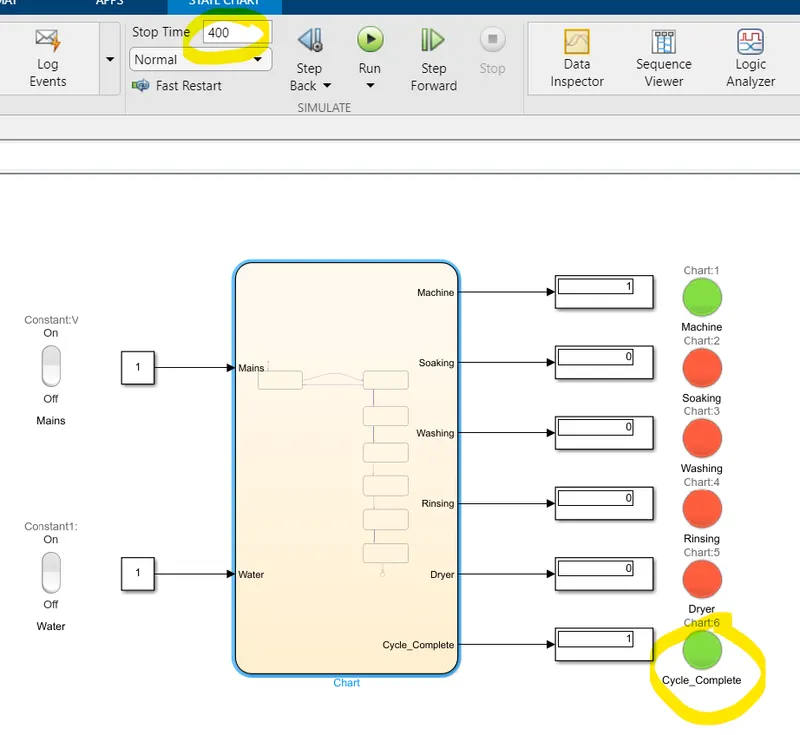
Result:
After simulating this model we can conclude that the state flow model we prepared in chart block is working fine as per our desired intention. We can change the timings of various states inside the chart block to delay the operations as per our wish. Also Lamp block gives us visual indications of the active and deactive states to easily understand the operation step by step.
Question 2:
2. Make a Simulink chart for the “Gear shift” logic as per below conditions:
Speed Range(kmph) Gear
0 to 15 1
16 to 25 2
26 to 40 3
41 to 60 4
Above 61 5
Give speed input while the simulation is running & display the gear number.
Solution:
To solve this, following steps are taken:
Steps:
1. Prepare a statflow block diagram using 'chart' block in simulink.
2. Create various states as per given conditions.
3. Assign proper types for the parametrs used in the diagram through symbols pane.
4. Create a simulink model to show outputs states through visual indications by using Lamp block.
5. Input a slider bar to act as an accelerator to change the speed in real time.
Procedure:
Following screeshot depitcts the blcok diagram arrangement of various states using chart block.
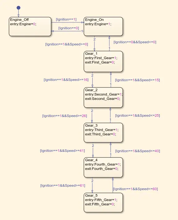
1. First state shows the status of engine, if its on or off, means if ignition of vehicle is started or not. This parameter is used as one of the inputs to the chart block in simulink model. Our car should not change the gears untill and unless its engine is turned on / ignited.
2. Next block checks if the input ignition id On or Off and accordingly it passes to next block.
3. This is first gear block, is is given in our conditions that, our car should be in first gear if our engine is on and the speed is greater than or equal to 0.
4. Next comes is second gear block, as per given conditions, once the vehicle achieves speed of 15 kmph, we should shoft to second gear, this block does exaclty the same, it monitors the speed, of cours engine should be on in all states to be true. once the speed is above 15 kmph, car runs in second gear.
5. Similar to second gear block, third gear block monitors the speed, if the speed is above 25kmph, car shifts from second gear to third gear.
6. Once the speed is achived at the level of 40kmph, car should make a shift from third gear to fourth gear.
7. As sson as the speed is at 60 kmph, car should go into fifth gear.
Following is symbols pane used for this excercise:
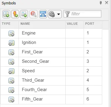
To model this in simulink and to show gear status, Lamp block has been used, which is already explained in the previous exercise. Now to change the speed of car in real time, we used a slider block, this changes the values at its output as per the slider position on the scale.
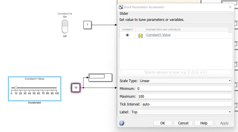
Following screenshots show the step by step operation and gear change with respect to the speed:
1. Ignition is off and hence engine is off.
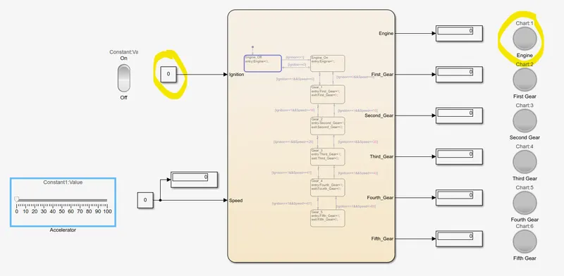
2. Ignition is on and engine is on and vehicle is running is first gear.
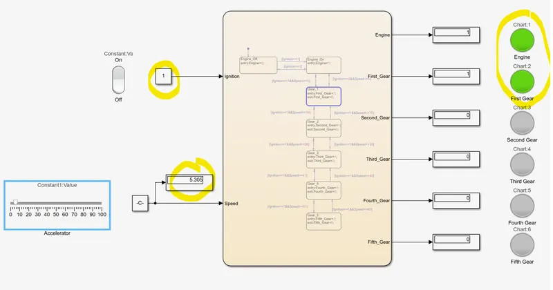
3. Speed is above 15kmph, vehicle is running in second gear.
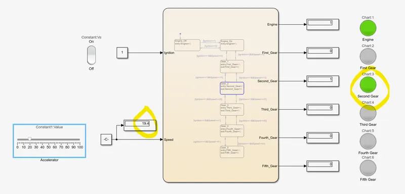
4. Speed is more than 25kmph and car is running at third gear.
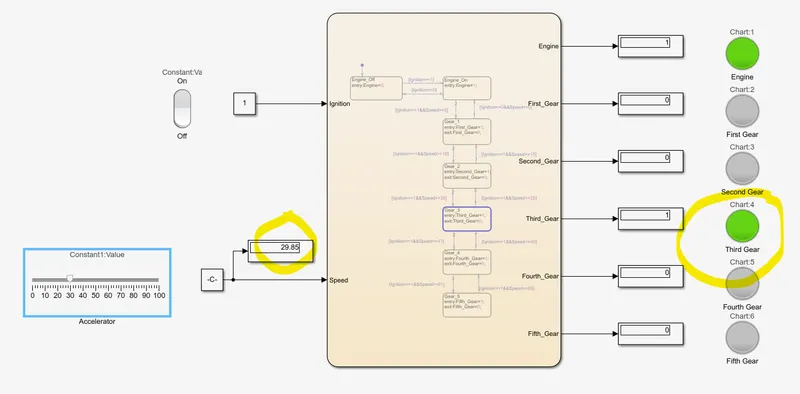
5. Speed is above 40 kmph and car is running in fourth gear.
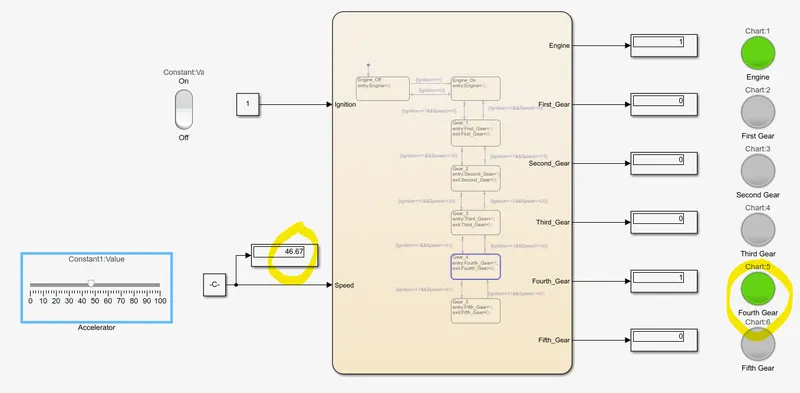
6. Speed is above 60kmph and car is running in fifth gear.
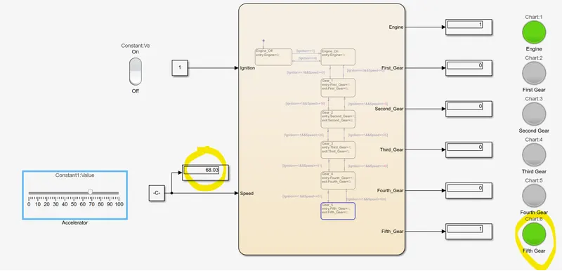
Result:
It can be seen that our stateflow logic for gear shift mechanism is working fine. Indicator lamps show the gear shift with respect to the speed variations.