Week - 4
1(Q).Implement control logic of a “washing machine” using Stateflow as per given sequence:
- If the power supply is available, the system gets activated
- If the Water supply is not available, stop the process & indicate through LED
- Soaking time should be 200s followed by Washing time of 100s.
- Then rinsing happens for next 20s & dryer runs for 50s ?
Sol:
Aim: To Implement the control logic of a "Washing machine" using Stateflow by the following conditions:
- If the power supply is available, the system gets activated
- If the Water supply is not available, stop the process & indicate through LED
- Soaking time should be 200s followed by Washing time of 100s.
- Then rinsing happens for next 20s & dryer runs for 50s
Procedure:
First, here we are using the pulse generator blocks to generate the both Power and Water supply. Some phase delay is added between the Power supply and Water supply generation to satisfy the given conditions. The complete simulink model is shown below:
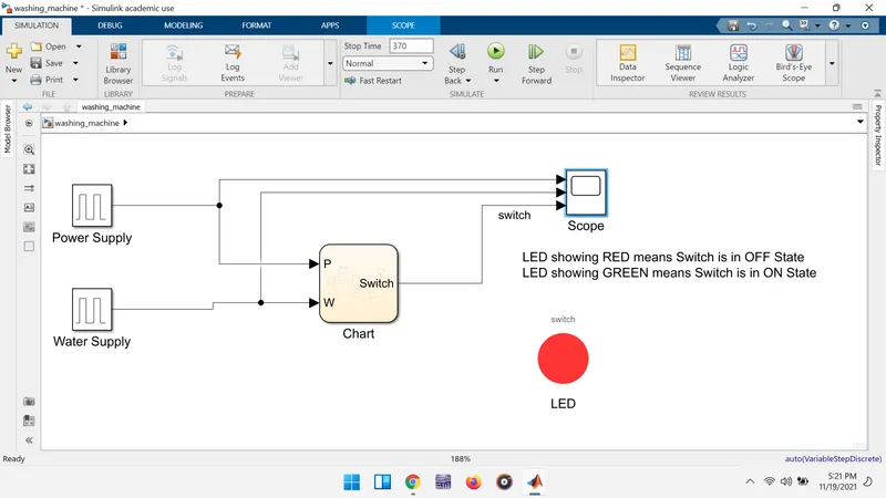
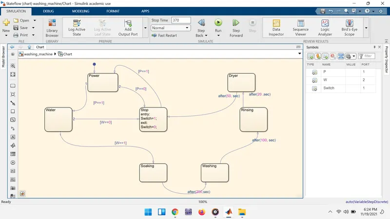
Chart model:
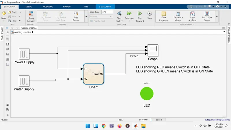
Condition-01: If the power supply is available, the system gets activated by turnning the LED on(i.e., GREEN light) as shown below figure:
Condition-02: If the Water supply is not available, stop the process & indicate through LED. Even though the power is ON but, the unavailability of makes the washing machine to stop as shown in the below figure: 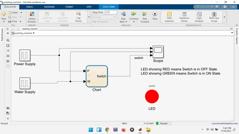
After the availability of water after some delay the power gets turned on and following process goes on.
After some time the washing machine is running with the following steps:
- Soaking is done for a duration of 200 seconds .
- Next, washing is taken place for 100 seconds.
- Next, the rinsing action took place for next 20 seconds and
- followed by the drying process for 50 seconds.
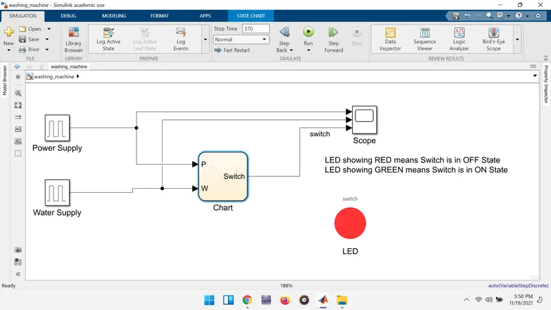
After completion of all the process the washing machine gets stopped as shown below:
Result:
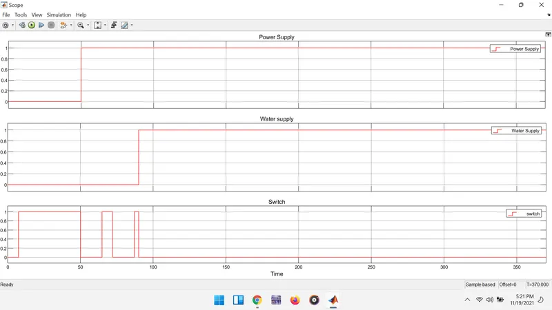
The power supply , water supply and switch action plots are shown in the below figure with respect to time.
2(Q). Make a Simulink chart for the “Gear shift” logic as per below conditions:
Speed Range(kmph) Gear
0 to 15 1
16 to 25 2
26 to 40 3
41 to 60 4
Above 61 5
Give speed input while the simulation is running & display the gear number?
Sol:
Aim: To make simulation chart for the "Gear Shift" as per below conditions:
Speed Range(kmph) Gear
0 to 15 1
16 to 25 2
26 to 40 3
41 to 60 4
Above 61 5
Procedure:
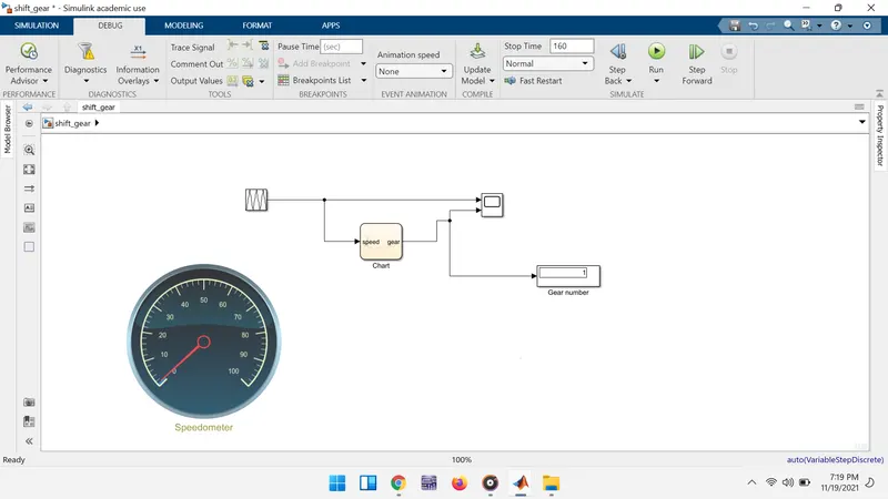
The acceleration is provided to vehicle by using the repeating sequence block according to time intervals the speed is increased and decreased. The followig simulation model represents the required conditions.
Flow chart:
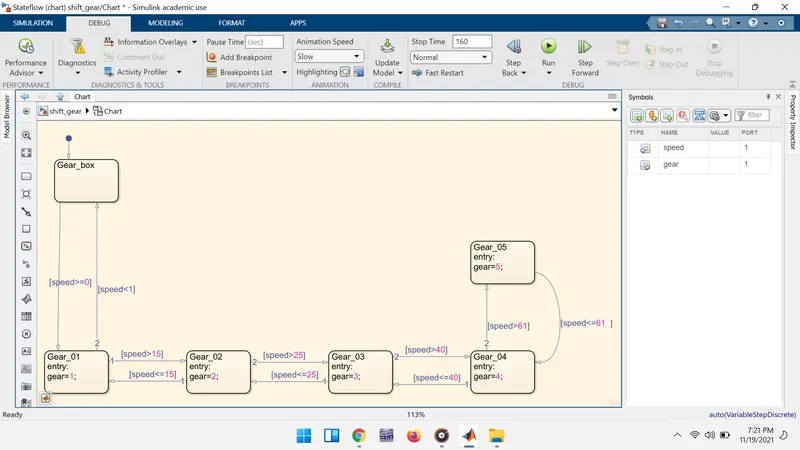
According the conditions given to the states the gears changes with the change in the speed and the speedometer indicates the speed.
Result:
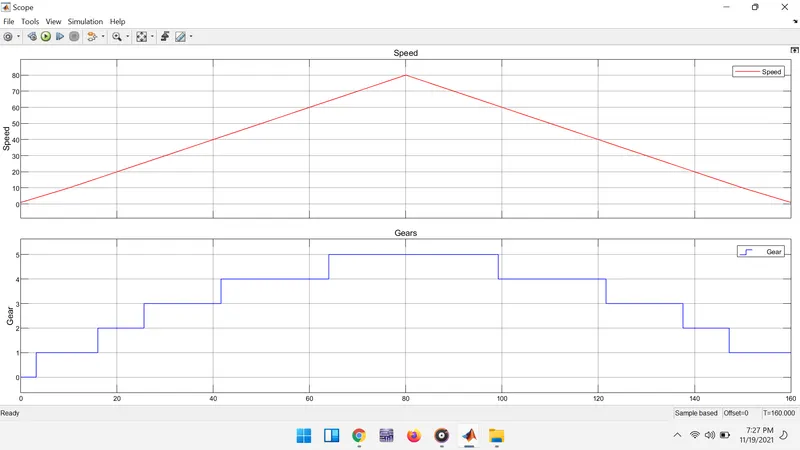
Finally , the plot of the speed and the gears are plotted in a graph as shown below: