Week -2
1)Sol:
Aim To develop the simulink model of doorbell using solenoid and observe the physical movement of plunger.
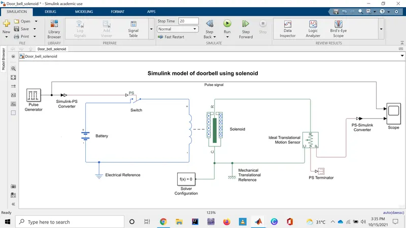
Simulink model
Working
To develop the required simulink model we use the following blocks:
- Pulse generator
- Simulink-PS Converter
- Switch
- Battery
- Solenoid
- Electrical reference
- Solver configuration
- Mechanical Translational Reference
- Ideal Translational Motion sensor
- PS terminator
- PS-Simulink Converter
- Scope
The pulse generator is used to generate the square pulse of the our requirement to ON and OFF the switch.

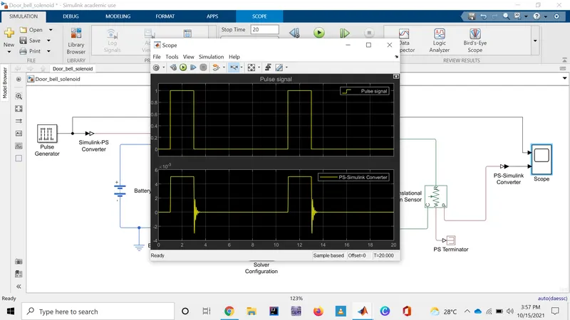
Here,the delay is taken 1 sec i.e.,the switch is on at 2 sec and is kept ON for 2 seconds as given condition and hence it is ON from t=2 to t=4.
During the ON period the electrical circuit is closed and the current flows in the solenoid then it generates the magnetic fields which is used to move the plunger up due to which it touch the bell to make the sound and OFF state the plunger comes back to its position.But , due the vibration it take some time to settle down as seen in below results.The movement of plunger is measured using the Ideal Translational Motion sensor.
Result
2)Sol:
Aim To use a thermistor to sense the temperature of a heater & turn on or turn off the fan.
Blocks used
- Signal Builder
- Simulink-PS and PS-Simulink Convereters
- Solver configuration
- Thermal Reference
- Controlled Temperature Source
- DC Voltage Source
- Thermistor
- Resistor
- Voltage Sensor
- Switch
- Scope
- Constant
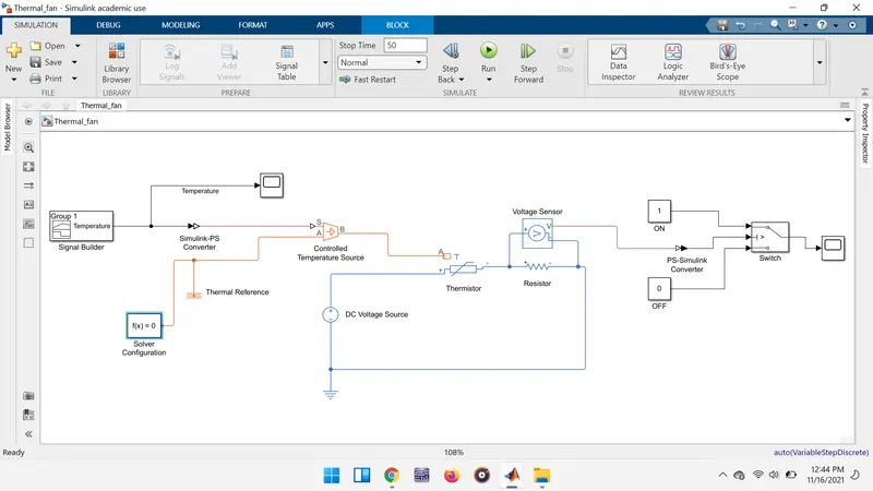
Simulink model
Working
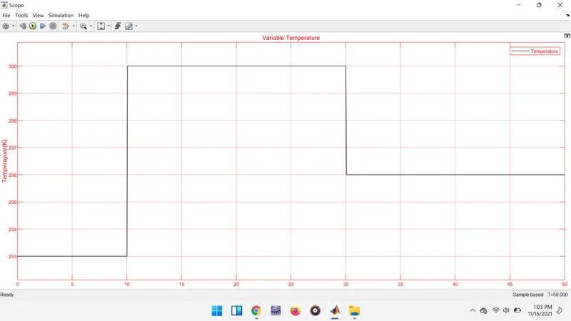
By using the singal builder the required variation in the temperature is generated as it varies in the reality.The Controlled temperature source is used to feed the temperature to the Thermistor in the circuit according which it changes it's resistance value and this variation of resistance cause the chages in the all parameters of the circuit and all also changes in the Resistor , which is assumed as the load.
As the thermistor varies the resistances value , then the current in the circuit also changes which leads to more heat in the load if the current value increases to high. And the voltage is used to measure the volatge across the load and the a particular threshold value is set to the switch to generate the logic accordingly.
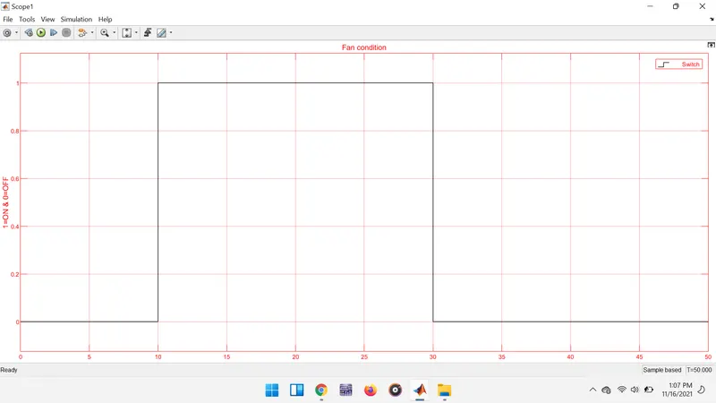
Here, the logic is high whenever the load is overheated , and then the fan is ON and when the logic low the fan is OFF.
Output
Variation in temperatue values:
Fan conditions: