Week - 4
Challenge 4
AIM
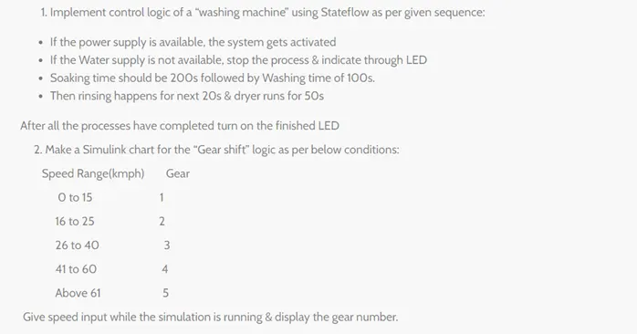
To implement control logic of a washing machine using stateflow as per given sequence:
- If the power supply is available, the system gets activated
- If the Water supply is not available, stop the process & indicate through LED
- Soaking time should be 200s followed by Washing time of 100s.
- Then rinsing happens for next 20s & dryer runs for 50s
STATEFLOW CREATION
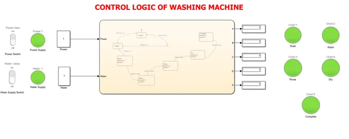
The charts are created as per prescribed conditions. The power and water supply must switch ON always to get the process to be completed. Otherwise, the process gets abort.
If the power and water supply conditions satisfied then only control goes to soak state followed by wash, rinse and dry as per prescribed delay time setting.
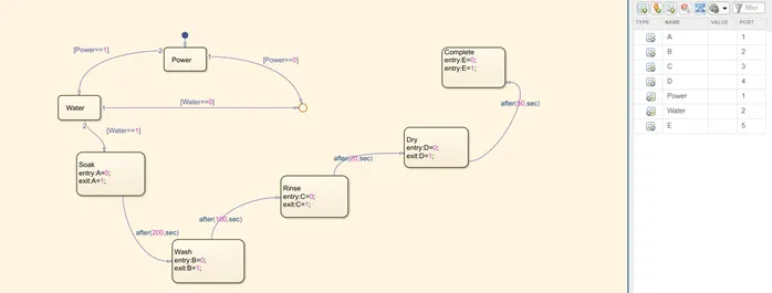
Figure – Stateflow chart
1. Power supply (OFF), Water supply (OFF)
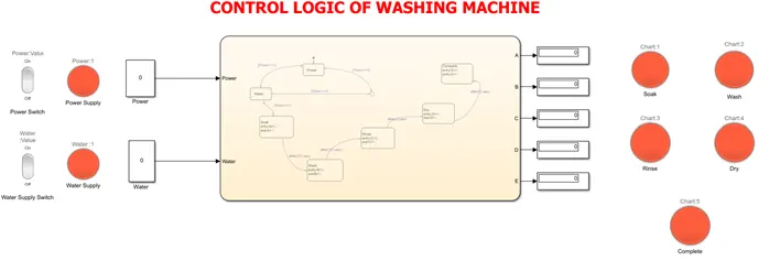
2. Power supply (ON), Water supply (OFF)
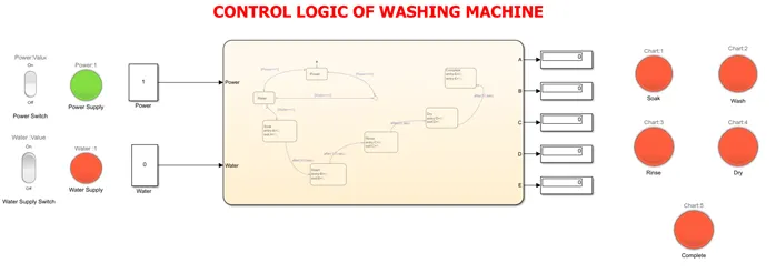
3. Power supply (OFF), Water supply (ON)
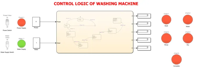
4. Power supply (ON), Water supply (ON), SOAK completed
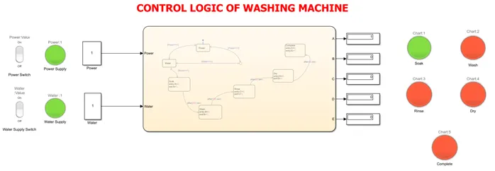
5. Power supply (ON), Water supply (ON), WASH completed
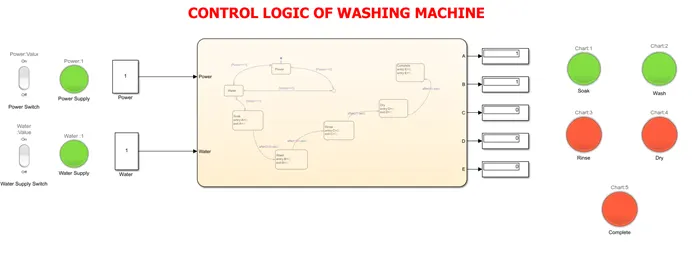
6. Power supply (ON), Water supply (ON), RINSE completed
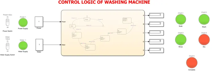
7. Power supply (ON), Water supply (ON), DRY completed
CONCLUSION
The control logic of washing machine has been performed with seven test cases shown above to meet the objectives.
------------------------------------------------------------------------------------------------------------------------------------------------------------
GEAR SHIFT LOGIC
AIM
To make a Simulink chart for the “Gear shift” logic as per below conditions:
|
Speed Range (Kmph) |
Gear |
|
0 to 15 |
1 |
|
16 to 25 |
2 |
|
26 to 40 |
3 |
|
41 to 60 |
4 |
|
Above 61 |
5 |
To give speed input while the simulation is running & display the gear number.
STATEFLOW CREATION
The charts are created as per prescribed conditions. The input to the chart is speed that get varied by using a ‘slider gain’ Simulink block. The gear is shifted by variations in speed. The display block is obtained to indicate the gear number based on speed input.
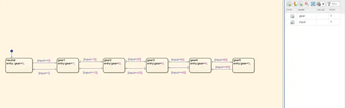
Figure – Sateflow chart
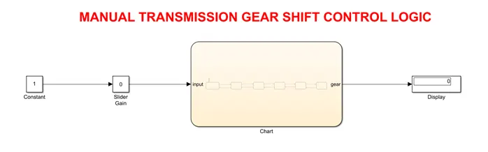
NEUTRAL
Input speed = 0 Kmph
Gear number = 0 (neutral)
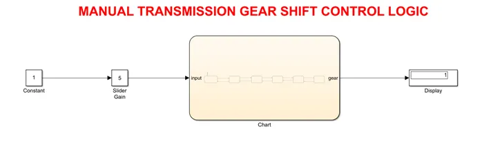
FIRST GEAR
Input speed = 5 Kmph
Gear number = 1
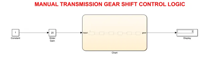
SECOND GEAR
Input speed = 20 Kmph
Gear number = 2
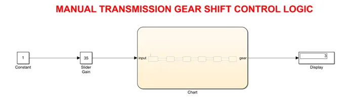
THIRD GEAR
Input speed = 35 Kmph
Gear number = 3
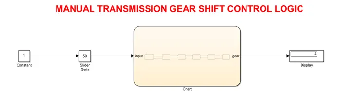
FOURTH GEAR
Input speed = 50 Kmph
Gear number = 4
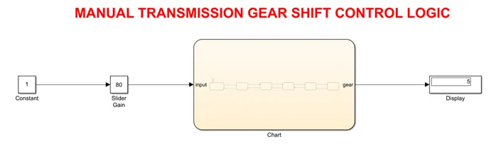
FIFTH GEAR
Input speed = 80 Kmph
Gear number = 5
CONCLUSION
The control logic of manual transmission gear shift logic has been performed with test cases shown above to meet the objectives.