Week - 4
Question.1:- implementation of control logic chart for washing machine using stateflow.
Aim :-
Make control logic chart for washing machine using stateflow.
Objective :-
- Make control logic chart for washing machine using stateflow.
- Show the process results through LED indicator.
Conditions for process :-
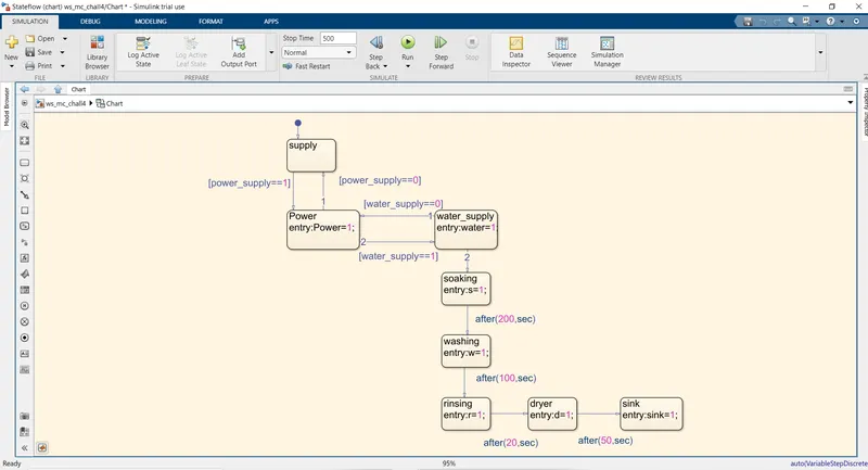
- if the power supply is available, the system gets activated.
- If the water supply is not available, stop the process & indicate through LED.
- Soaking time is 200sec and washing time is 100 sec.
- Rinsing time is 20sec and then dryer runs for 50 seconds.
Simulink model :-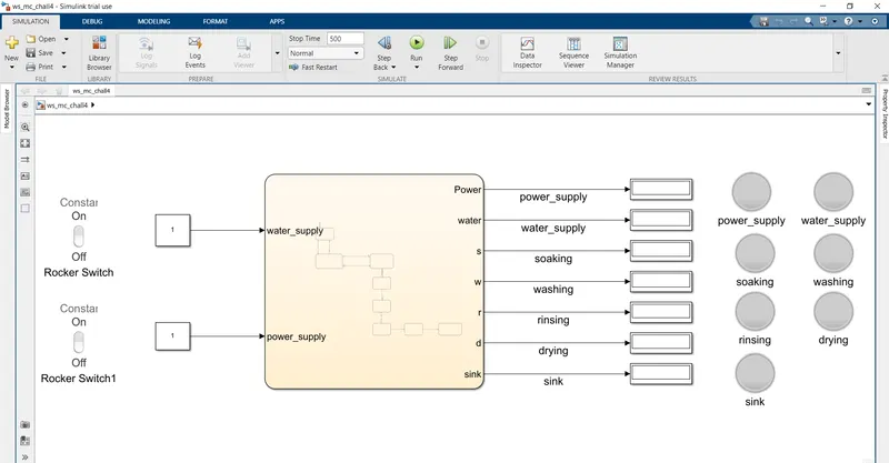
Process :-
- Creating blank model in Simulink and search for chart block.
- Open the chart block and take the junction feature from the stateflow window.
- Define the blocks with proper given conditions.
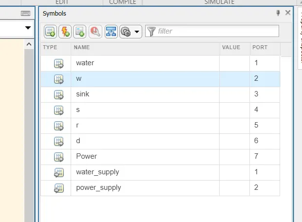
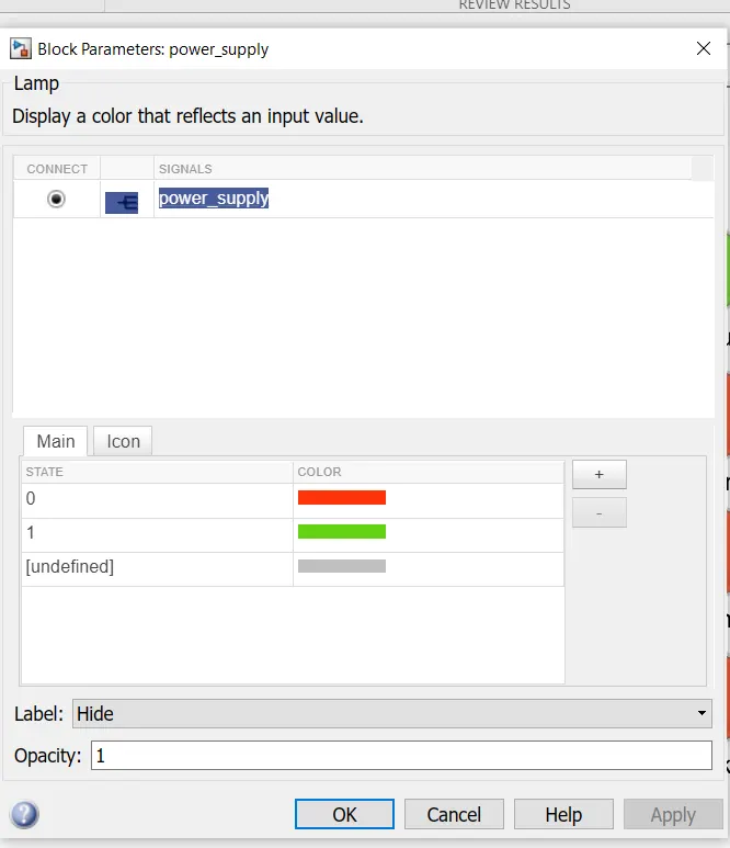
- Select signal pane and define an output and an input data.
- Take the blocks of lamp and connect to the outputs.
- Taking constant block and rocker switch connected to input.
- Run the simulation for 500 seconds.
Signal pane :-
Blocks used :-
- chart :- complete stateflow is made in this block.
- Rocker switch:- for giving the inputs of power supply.
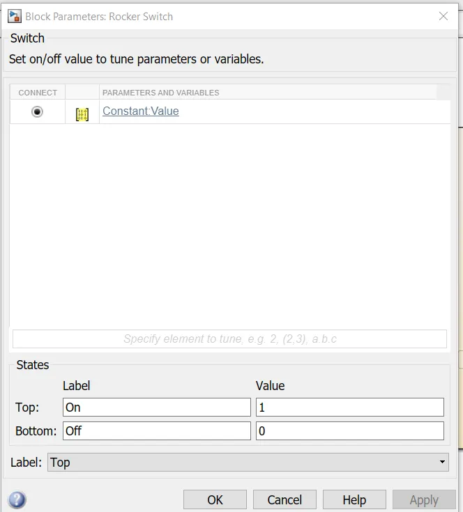
- Constant :- for giving the input values which are defined to operate switch and water suppy.
- Display :-it shows the output value of block connected to it.
- Lamp :- it indicated the output of the blocks connected to it by blowing different lights.
Results :-
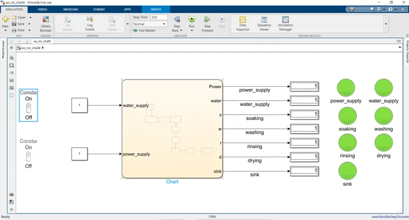
Constant shows 1 for power and water supply as inputs hence all the processes of washing machine is done showing the LED indicator lights.
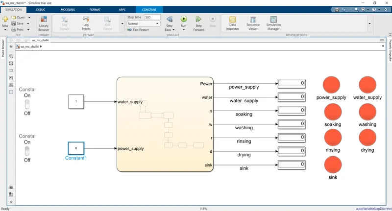
Here 0 is given as input which indicated power supply is off hence washing machine will not on and no process will be completed.
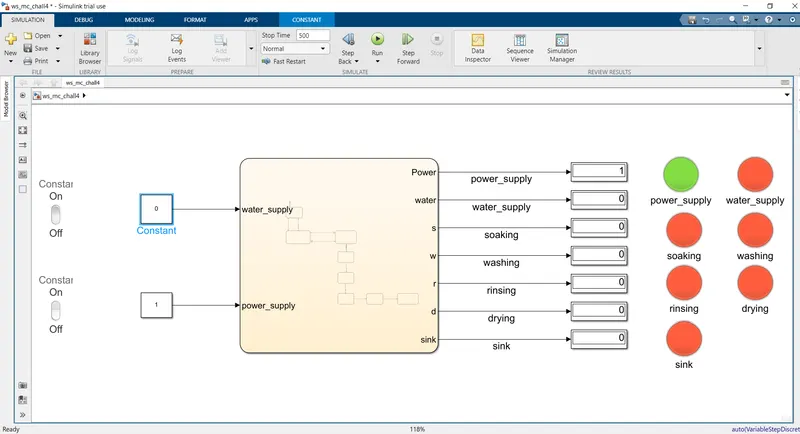
processes are incomplete shown in the Here we gave the power supply but water supply is off hence machine will on but washing lamp.
Question.2 :- Make a simulation chart for “Gear shift” logic
Aim :- make a simulation for gear shift logic.
Objective :-
- make a simulation for gear shift logic.
- Give speed input while simulation is running and display the gear number.
Condition of process :-
Speed range(kmph) Gear no.
0 to 15 1
16 to 25 2
26 to 40 3
41 to 60 4
Above 61 5
Simulink model :-
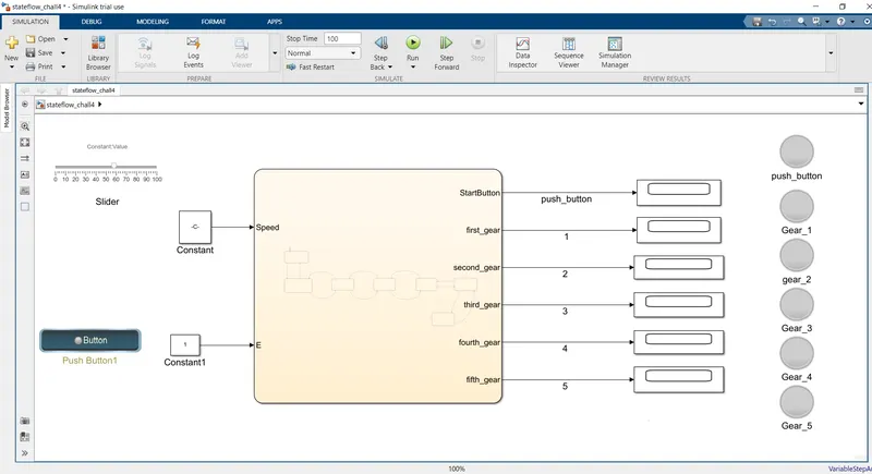
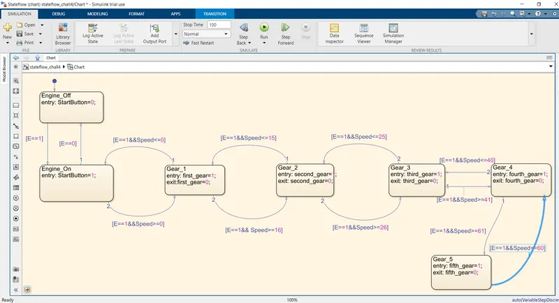
Process :-
- Taken chart block in simulink blank model.
- Open the chart block and take the stateflow junction blocks and give them proper condtions by joining them.
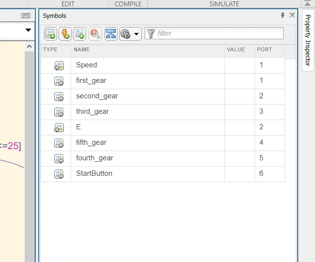
- Using signal pane we define the input and output data.
- Taken display and lamp blocks for output.
- Taken constant and push button block for input data.
Signal pane :-
Blocks used :-
- chart :- complete stateflow is made in this block.
- Push button :- we provide the input conditions to push block to ON/OFF.
- Slider :- we used slider to give speed input to the system.
- Constant :- for giving the input values which are defined to operate switch and water supply.
- Display :-it shows the output value of block connected to it.
- Lamp :- it indicated the output of the blocks connected to it by blowing different lights.
Results :-
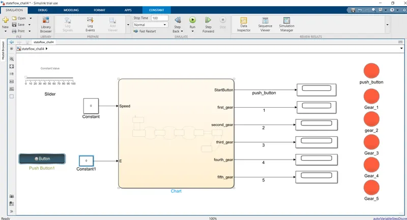
Here we gave 0 as input to engine hence push button is not engaged and vehicle does not started hence no gear is engaged.
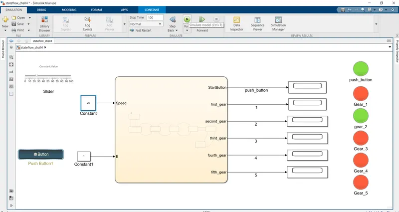
Here engine is on as 1 is given as the input and speed input given is 25kmph hence according to given conditions second gear is engaged.
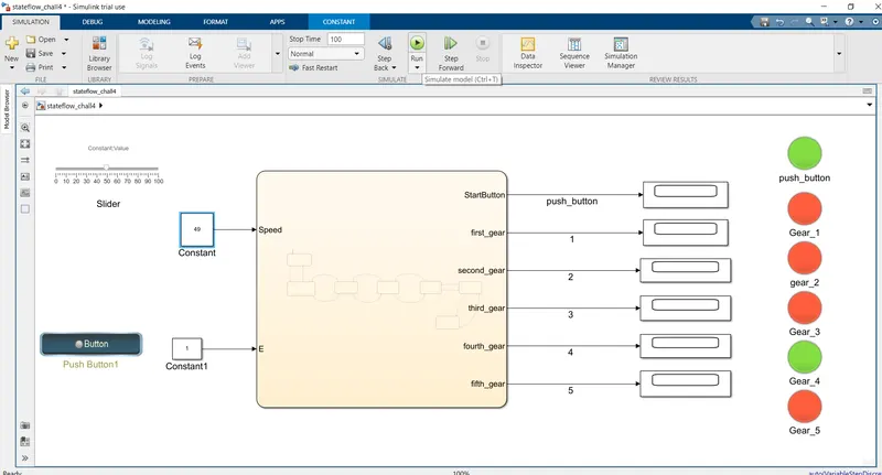
Here speed input given is 49kmph hence gear engaged is fourth gear.