Week -2
Simulink model of Doorbell :-
Aim :-
making Simulink model of doorbell using solenoid
Objective :-
- making the Simulink model of doorbell using solenoid.
- operating doorbell for every 2 seconds for given period of time by closing the switch and observe the results.
Theory :-
Doorbell is a electromagnetic device. When the power source is applied and switch is closed the electromagnetic field is developed in the copper windings and it attracts the soft iron armature. Hammer is mounted on armature which strikes on the gong and bell rings.
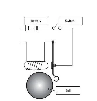
Simulink model :-
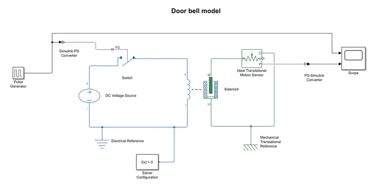
Simulink block used :-
- pulse generator :- to generate the time signals to control the switch operation.
- Simulink-PS converter :- to convert Simulink environment into real time environment.
- Switch :- to ON or OFF the power supply.
- DC voltage source :- to give power to run the system.
- Solenoid :- to generated magnetic field to attract the iron core.
- Ideal translational motion sensor :- converts mechanical variables measured into the signals proportional to the velocity or position.
- Scope :- to view the graph of the signals.
- Electrical ground :- to surpass the extra energy through ground.
- Mechanical ground :- it shows all translational ports are rigidly clamped to the frame.
Working process :-
- In the pulse generator signals are generated for every 2 seconds to control the switch to ring the bell.
- Generated signals are converted into the real time environment through Simulink- PS converter.
- According to the signals switch operates and the flow of current is given to solenoid through the Dc power source.
- Solenoid generates the magnetic field which attracts the armature.
- From the solenoid motion is sensed by ideal motion sensor and signals are converted into Simulink Environment to record the motion of the hammer.
Results :-
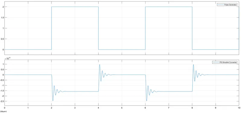
From the results we can see that the switch is close for every 2 seconds and the bell rings after every 2 seconds of gap for the given 10 seconds of time period. We can see the displacement of armature in the graph by using ideal translational motion sensor.
Simulink of a cooling fan operated by thermistor :-
Aim :-
Making Simulink model for thermistor operated heater cooling fan
Objective :-
- Making Simulink model to turn ON/OFF heater cooling fan by sensing temperature by thermistor.
- Study the results obtained.
Theory :-
Thermistor :-
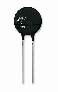
A thermistor is a type of resistor whose resistance is strongly dependent on temperature. Word is combination of thermal and resister. We are using “NTC thermistor” which means negative temperature coefficient thermistor. In these type of thermistors if temperature increases resistance will decrease. Thermistor material used is basically metal oxides eg. Chromium, manganese, cobalt, nickel.
Negative temperature coefficient thermistor (NTC):-
Simulink model :-
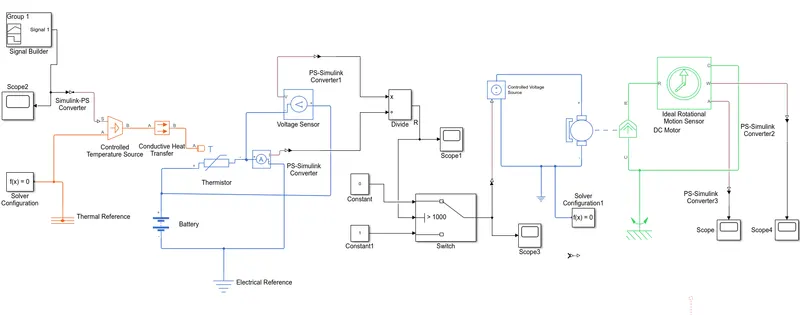
Simulink block used :-
- signal builder :- The Signal Builderblock allows you to create interchangeable groups of piecewise linear signal sources and use them in a model. You can quickly switch the signal groups into and out of a model to facilitate testing. In the Signal Builder window, create signals and define the output waveforms.
- Scope :- To view the graph of the signals.
- Simulink-PS converter :- to convert Simulink signal into physical signal.
- Thermistor :- To sense the temperature to produce resistance.
- Battery :- To provide power source.
- Voltage sensor :- To sense the voltage across the circuit.
- Switch :- To control the resistance output at particular threshold value.
- Controlled voltage source :- To supply voltage according to the physical signal ports.
- DC Motor :- To run at controlled voltage.
- Ideal rotational motion sensor :- to sense the motions of DC Motor.
- Electrical and Mechanical references :- to show that systems are grounded properly.
Working process :-
- We give the input heat source conditions to signal builder.
T = 20 degree C for 0 – 10 seconds
T = 27 degree C for 10 – 30 seconds
T = 23 degree C for 30 – 50 seconds
- Then controlled temperature source is sensed by the thermistor in which resistance is varied with the changing temperature.
- From the signal of the resistance the motor of colling fan is operated according to given conditions.
- Output of DC motor is sensed by ideal rotational motion sensor.
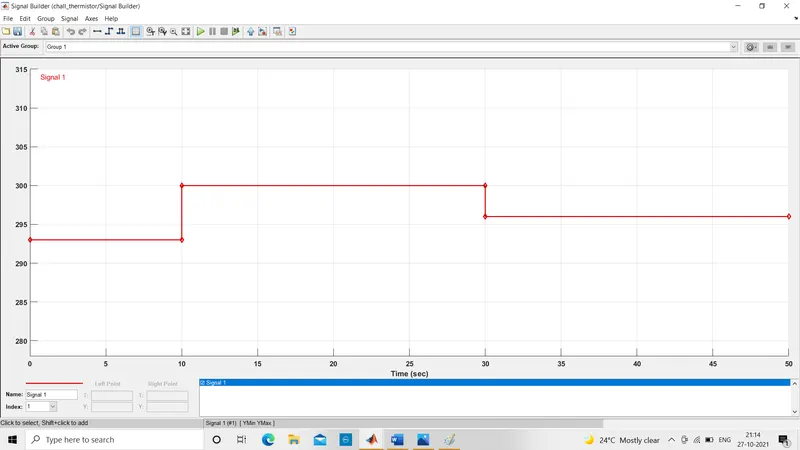
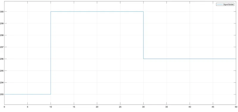
Above graph shows the signal is build for given temperature ranges.
Results :-
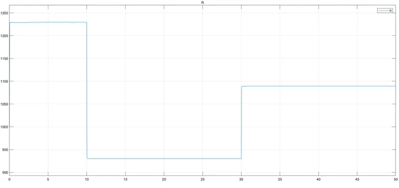
Above graph shows time VS resistance plot, here resistance is decreasing with increase in temperature.
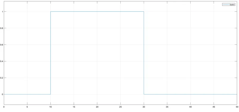
This graph shows the signal outputs of switch.
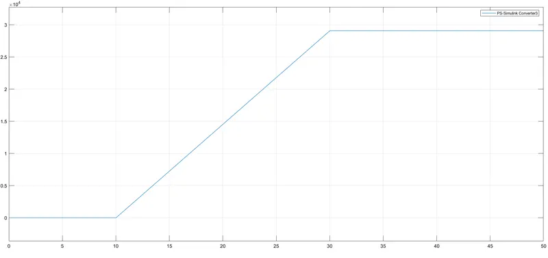
Time vs Angular Displacement :-
Time vs Velocity :-
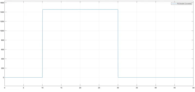
Above two graph shows that when the temperature is exceeded above 25 degree C then fan is turned ON.
References :-
- Matlab helpbook
- Wikipedia