Week - 4
Aim
Implement control logic of a “washing machine” using Stateflow as per given sequence:
- If the power supply is available, the system gets activated
- If the Water supply is not available, stop the process & indicate through LED
- Soaking time should be 200s followed by Washing time of 100s.
- Then rinsing happens for next 20s & dryer runs for 50s
Introduction
Stateflow provides a graphical language that includes state transition diagrams, flow charts, state transition tables, and truth tables. You can use Stateflow to describe how MATLAB algorithms and Simulink models react to input signals, events, and time-based conditions.
Stateflow enables you to design and develop supervisory control, task scheduling, fault management, communication protocols, user interfaces, and hybrid systems.
With Stateflow, you model combinatorial and sequential decision logic that can be simulated as a block within a Simulink model or executed as an object in MATLAB. Graphical animation enables you to analyze and debug your logic while it is executing. Edit-time and run-time checks ensure design consistency and completeness before implementation.
Function of the Chart
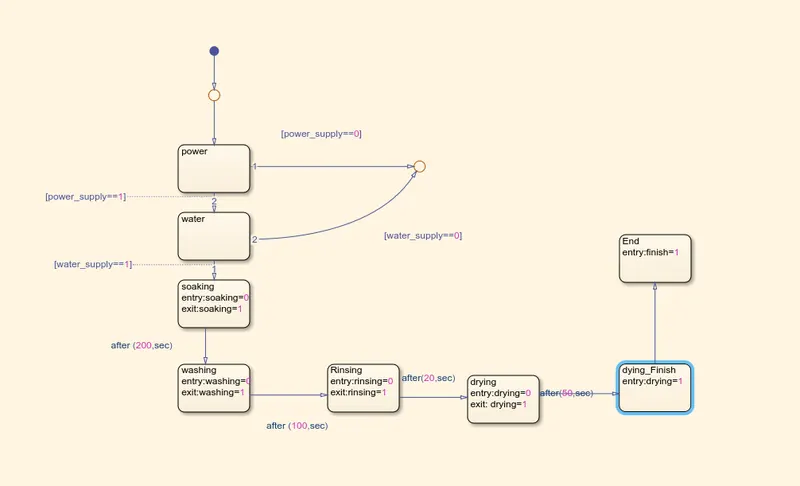
1) If power supply is available then is mentioned as (power_supply==1) and if power supply is not available then it is mentioned as (power_supply==0)
2) If power supply is available then moves to the next state that is water if not if power_supply==0 then moves to junction
3) If water supply is available that is water_supply==1 then moves to the next state that is soaking if not that is if water_supply==0 then moves to the junction
4) Immediately after entering the soaking state, Lamp indicates no colour (as entry is mentioned 0 which is not defined) and after 200secs when the soaking state exits the lamp indicated green colour (as exit is mentioned 1)
5) Immediately after entering the washing state, Lamp indicates no colour (as entry is mentioned 0 which is not defined) and after 100secs when the washing state exits the lamp indicated green colour (as exit is mentioned 1)
6) Immediately after entering the rinsing state, Lamp indicates no colour (as entry is mentioned 0 which is not defined) and after 20secs when the rinsing state exits the lamp indicated green colour (as exit is mentioned 1)
7) Immediately after entering the drying state, Lamp indicates no colour (as entry is mentioned 0 which is not defined) and after 50secs when the drying state exits the lamp indicated green colour (as exit is mentioned 1)
8)Immediately after entering the finish state, Lamp indicates green colour (as entry is mentioned 1)
Result
When power supply is turned off(indicated by red ) and water supply is turned on (indicated by green) none of the process will run
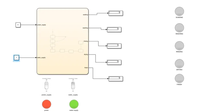
When power supply is turned on (indicated by green) and water supply is turned off(indicated by red) none of the process will run
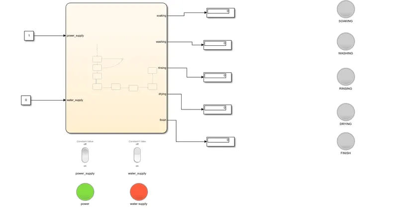
When power supply is turned off (indicated by red) and water supply is turned off(indicated by red) none of the process will run
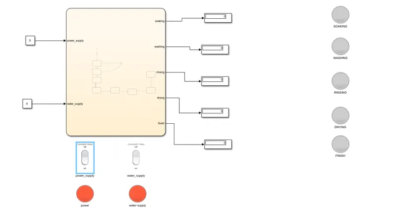
When both power supply and water supply is turned on (indicated by green) the process will move to the next step that is soaking and after 200sec ,once the soaking is complete the lamp mentioning soaking will turn green
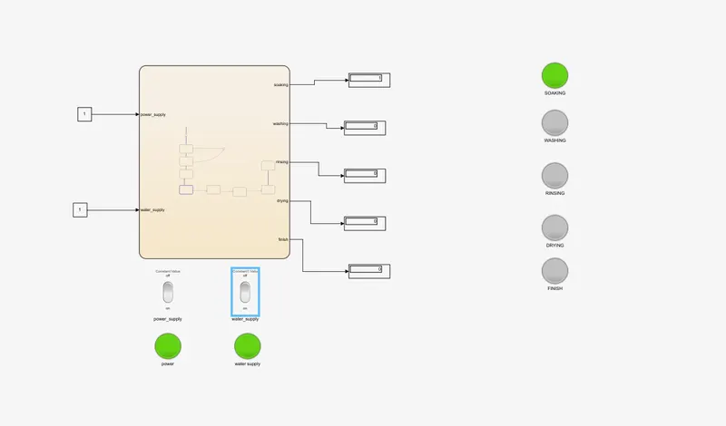
The process will move to the next step that is washing and after 100secs ,once the washing is complete the lamp mentioning washing will turn green
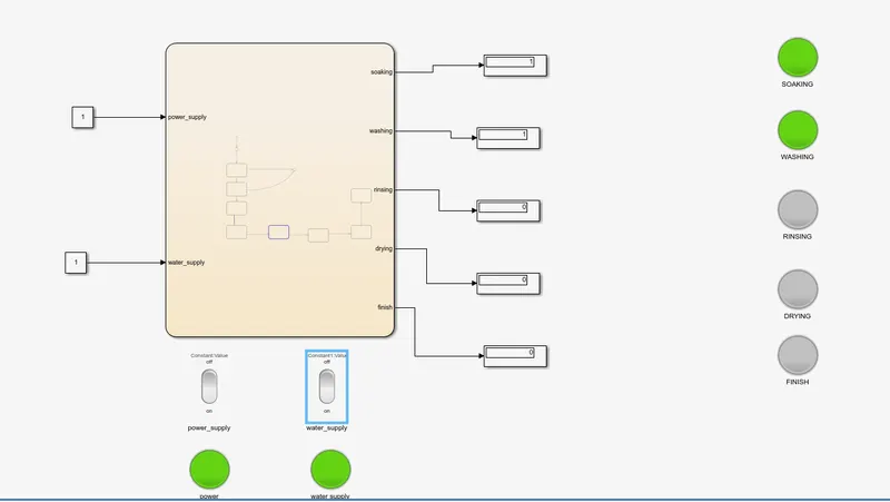
The process will move to the next step that is Rinsing and after 20secs ,once the rinsing is complete the lamp mentioning rinsing will turn green
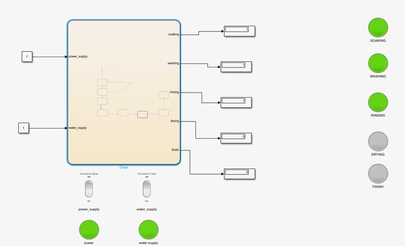
The process will move to the next step that is drying and after 50secs ,once the drying is complete the lamp mentioning drying will turn green
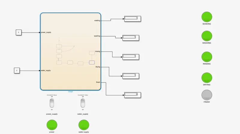
Finally after the lamp mentioning drying has turn green , the lamp mentioning finish will also turn green and is ready to take the clothes out of washing machine.
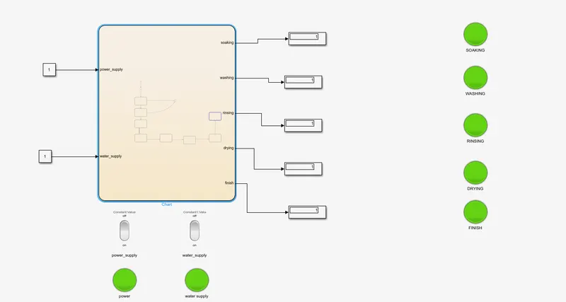
Implement control logic of a “washing machine” using Stateflow as per given sequence in much more sophisticated design.
Function of the Chart
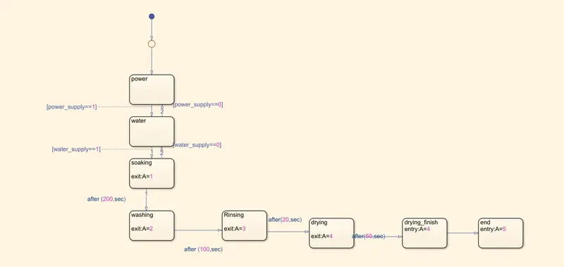
1) If power supply is available then is mentioned as (power_supply==1) and if power supply is not available then it is mentioned as (power_supply==0)
2) If power supply is available then moves to the next state that is water if not if power_supply==0 then remains at the state power
3) If water supply is available that is water_supply==1 then moves to the next state that is soaking if not that is if water_supply==0 then remains at the state water
4) Immediately after entering the soaking state, Lamp indicates no colour and after 200secs when the soaking state exits the lamp indicated marron colour (as exit is mentioned 1)
5) Immediately after entering the washing state, Lamp indicates no colour and after 100secs when the washing state exits the lamp indicated Pink colour (as exit is mentioned 2)
6) Immediately after entering the rinsing state, Lamp indicates no colour and after 20secs when the rinsing state exits the lamp indicated purple colour (as exit is mentioned 3)
7) Immediately after entering the drying state, Lamp indicates no colour and after 50secs when the drying state exits the lamp indicated yellow colour (as exit is mentioned 4)
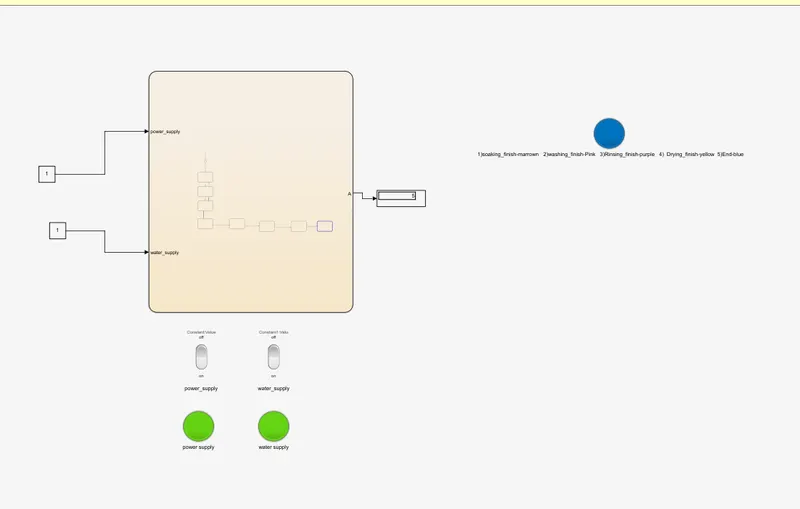
8)Immediately after entering the finish state, Lamp indicates blue colour (as entry is mentioned 4)
Result
When power supply is turned off (indicated by red) and water supply is turned off(indicated by red) none of the process will run
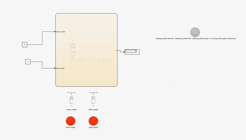
When power supply is turned on (indicated by green) and water supply is turned off(indicated by red) none of the process will run
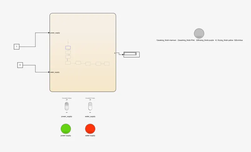
When power supply is turned off(indicated by red ) and water supply is turned on (indicated by green) none of the process will run
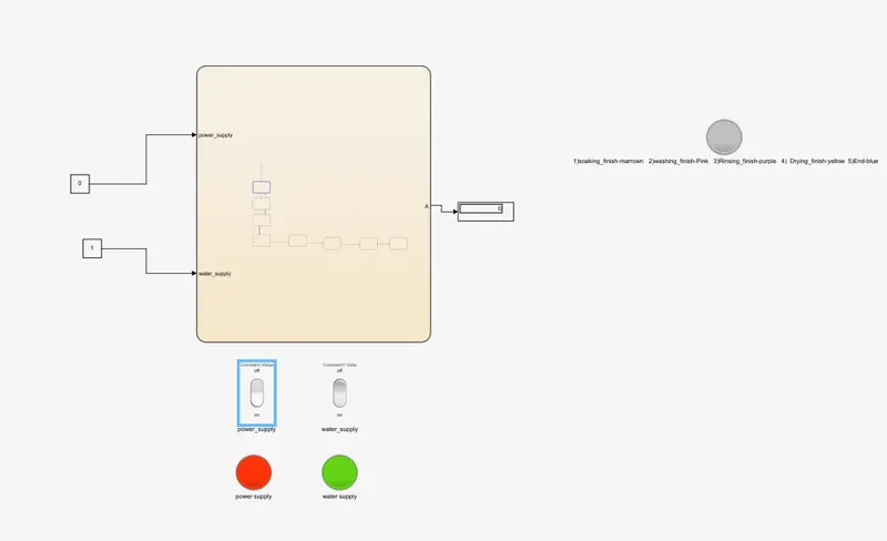
When both power supply and water supply is turned on (indicated by green) the process will move to the next step that is soaking and after 200sec ,once the soaking is complete the lamp mentioning soaking will turn marron
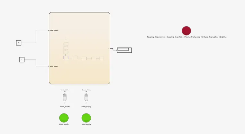
The process will move to the next step that is washing and after 100secs ,once the washing is complete the lamp mentioning washing will turn pink
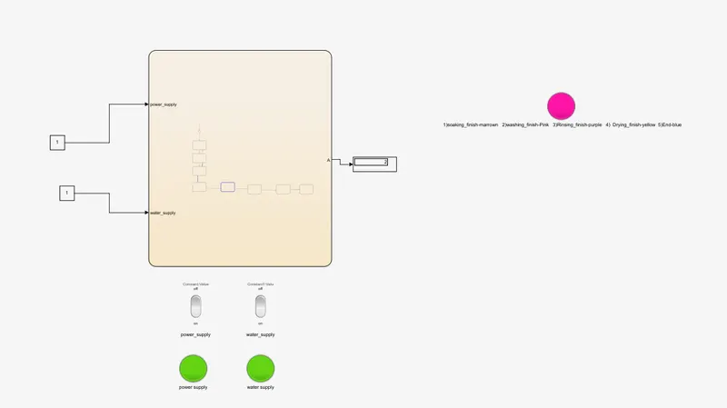
The process will move to the next step that is Rinsing and after 20secs ,once the rinsing is complete the lamp mentioning rinsing will turn purple
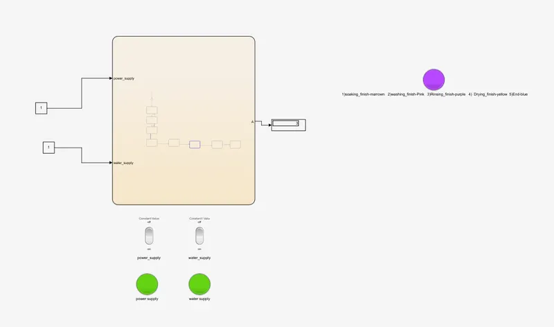
The process will move to the next step that is drying and after 50secs ,once the drying is complete the lamp mentioning drying will turn yellow
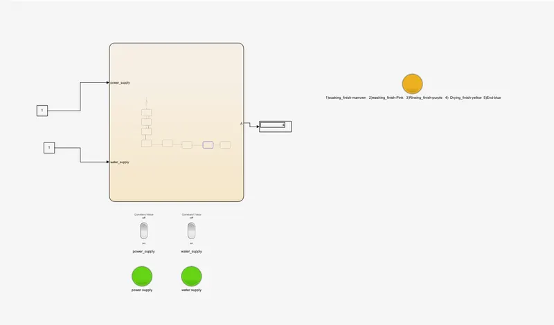
Finally after the lamp mentioning drying has turn yellow , the lamp mentioning finish will turn blue and is ready to take the clothes out of washing machine.
Aim
Make a Simulink chart for the “Gear shift” logic as per below conditions:
Speed Range(kmph) Gear
0 to 15 1
16 to 25 2
26 to 40 3
41 to 60 4
Above 61 5
Introduction
Stateflow provides a graphical language that includes state transition diagrams, flow charts, state transition tables, and truth tables. You can use Stateflow to describe how MATLAB algorithms and Simulink models react to input signals, events, and time-based conditions.
Stateflow enables you to design and develop supervisory control, task scheduling, fault management, communication protocols, user interfaces, and hybrid systems.
With Stateflow, you model combinatorial and sequential decision logic that can be simulated as a block within a Simulink model or executed as an object in MATLAB. Graphical animation enables you to analyze and debug your logic while it is executing. Edit-time and run-time checks ensure design consistency and completeness before implementation.
Functioning of the chart
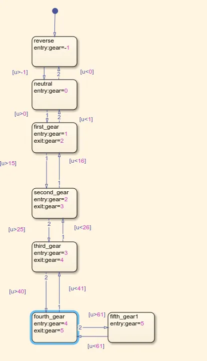
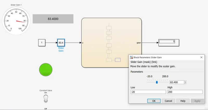
1)If the input value entered is lesser than-1(u<-1) then the gear remains in reverse gear
2) If the input value entered is greater than-1(u>-1) and lesser than 1(u<1) the gear is at neutral
3)If the input value entered is greater than 0(u>0) and lesser than 16(u<16) the gear is at first gear
4)If the input value entered is greater than 15(u>0) and lesser than 26(u<26) the gear is at second gear
5) If the input value entered is greater than 25(u>25) and lesser than 41(u<41) the gear is at third gear
6)If the input value entered is greater than 40(u>0) and lesser than 61(u<61) the gear is at fourth gear
7)abvove 61 is 5th gear
explanation of entry and exit by the means of the example
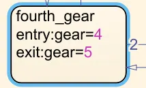
entry :gear=4 (when it enters the fouth_gear state it means that it is in 4th gear)
exit:gear=5 (when it exits the fouth_gear state it means that it is in 5th gear)
Meaning of the numericals indicated in the display block
Meaning of the numericals indicated in the display block
'-1'-reverse gear
'0'- Neutral gear
'1' -first gear
'2'- second gear
'3' - third gear
'4'- fourth gear
'5' - fifth gear
Result
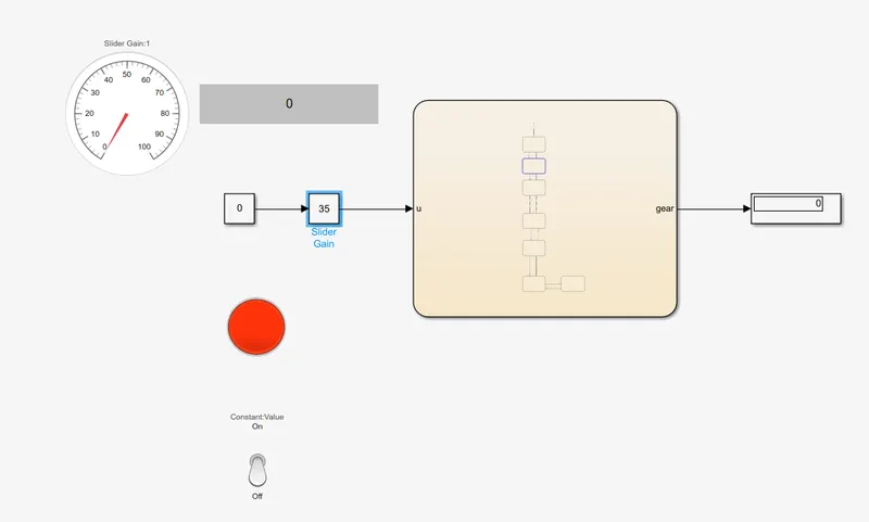
Before the engine start the lamp is indicated in red
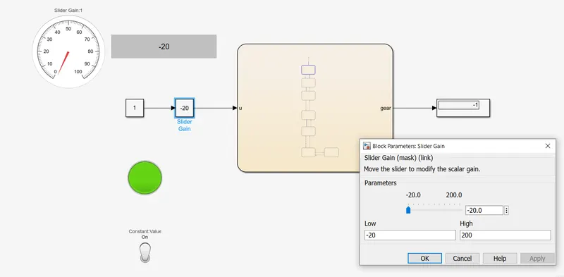
After the engine start the lamp is indicated in green and while the simulation is running the slider block is used to change the input values and when the negavtive value is given as the input it represents reverse gear(-1) in the display
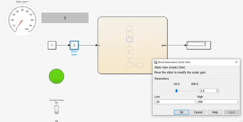
similarly while the simulation is running the slider block is used to change the input values and is given as 2 which represents 1st gear(1) in the display
when the value is indicating 24 it displays 2nd gear(2)
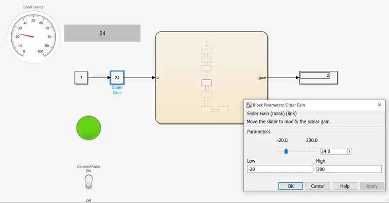
when the value is indicating 32 it displays 3rd gear(3)
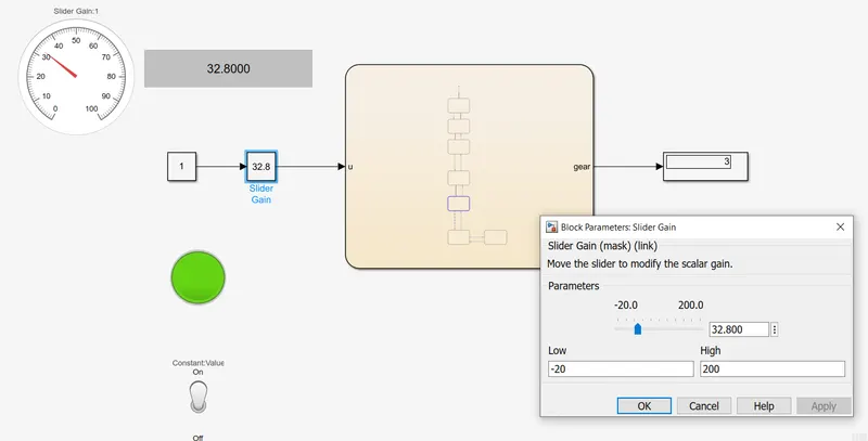
when the value is indicating 45 it displays 4th gear(4)
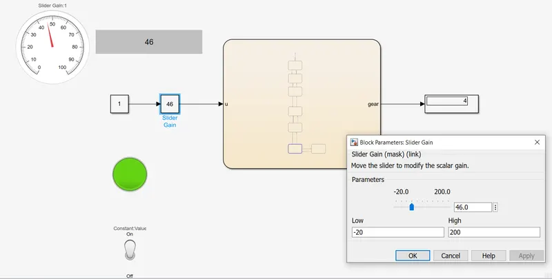
when the value is indicating 32 it displays 5th gear(5)