Week - 4 - 2D meshing for Plastic components
Week - 4 - 2D meshing for Plastic components
Objective:
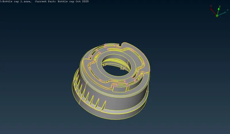
To extract the mid surface and mesh the given bottle cap component using given quality criteria and assign correct thickness to the property.
|
S.No |
Quality Criteria |
Value |
|
1 |
Target/Average length |
1 |
|
2 |
Minimum Length |
0.5 |
|
3 |
Maximum Length |
3 |
|
4 |
Aspect |
3 |
|
5 |
Warpage |
15 |
|
6 |
Skewness |
45 |
|
7 |
Jacobian |
0.7 |
|
8 |
Minimum Quad Angle |
45 |
|
9 |
Maximum Quad Angle |
135 |
|
10 |
Minimum Tria Angle |
30 |
|
11 |
Maximum Tria Angle |
120 |
|
12 |
Tria Percentage |
15 |
Objective
-
This task aims to clean up topology and correct geometric errors.
-
Midsurface generated from the 3D Plastic Bottle Cap model.
-
Assign thickness to them based on surface thickness by creating a Part set.
-
Meshing of the 2D midsurface model with the necessary quality criteria.
|||||||||||||||||||||||||||||||||||||||||||||||||||||||||||||||||||||||||||||||||||||||||||||||||||||||||||||||||||||||||||||||||||||||||||||||||||||||||||||||||||
Procedure
Geometry Cleanup:
-
Import the CAD mode of Plastic Bottle Cap in Ansa.
-
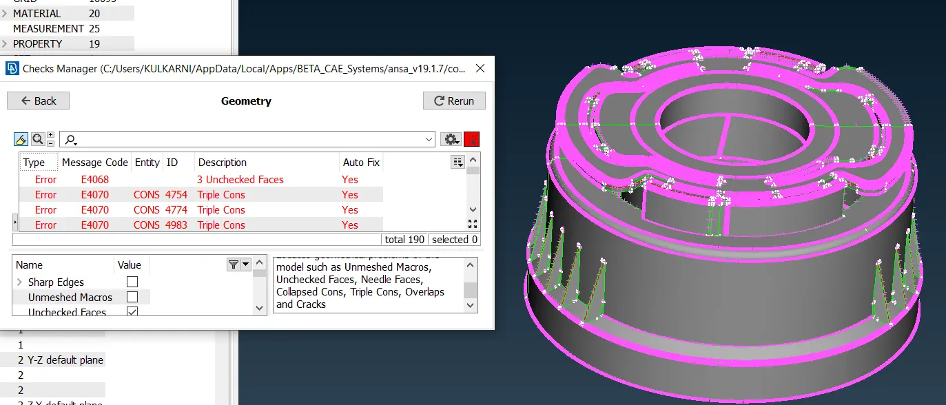
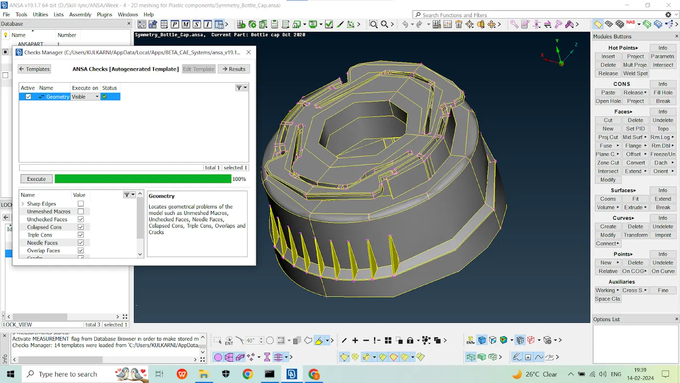
Perform check for Geometry.
-
In above image, we can see some geometrical errors in the model.
-
By selecting and applying “Fix”, we remove the errors and manual we can alter the cons, hot points and use topo to stitch the surfaces.
Midsurfacing:
After geometry cleanup, we can use the "Midsurface" option to create a component's midsurface, or we can manually create a midsurface for each surface.
There are various options for creating midsurfaces automatically based on the requirements of different types of components.
There are several options for automatic midsurfacing, including skin, casting, and welding.
However, the Plastic Bottle Cap model is very small and complex, which can result in a poor midsurface when using automatic options, or it may be difficult to generate the midsurface automatically for these types of components.
So, for each surface, we will manually create a midsurface.
Because the thickness varies from surface to surface, we will define a PID for each midsurface or group of midsurfaces and apply the thickness to them.
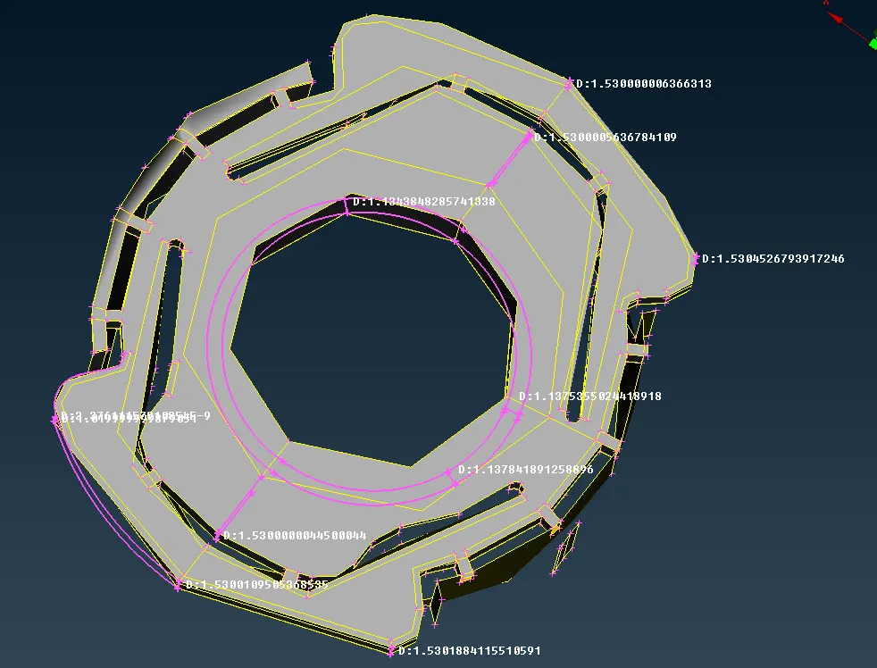
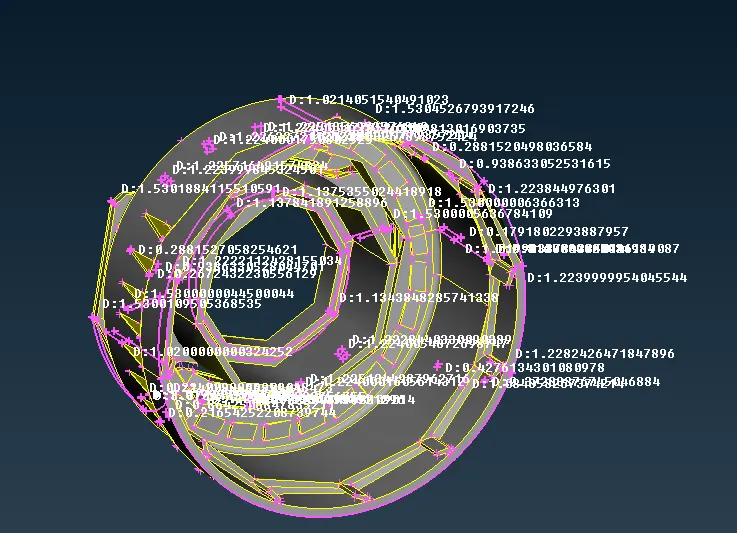
To create a midsurface, the first step is to measure the thickness, which can be done using node-to-node distance or, if that is not possible, we can create spots, lines, or points, project them onto another surface, and measure by selecting them.
Once we know the thickness, we can select "Offset" under the faces option, enter the half value based on the thickness, and create a midsurface for selection.
After using "Offset", we can offset the surface by value.
There are some surfaces with variable thickness, which cannot be directly offset.
For those areas, we can create the midsurface by different methods.
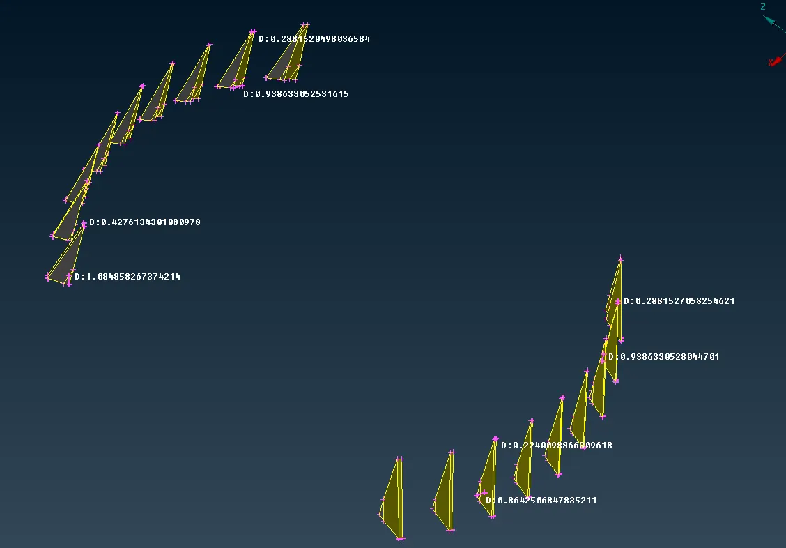
The model's thickness varies on some surfaces. These surfaces are extracted using the middle tool in the topo module topo-faces-middle (single or multi). We can use both for ribs, but the surfaces are only one. Use middle-single. Now select the first surface and then click the second surface. Now click OK to accept the surface. Now the midsurface is created.
The model's inner bottom contains ribs of varying thickness. Use topo-faces-middle to create a midsurface for the rib, then extend the free edge. topo-faces-extend selects the free edge and the midsurface that is connected to another major midsurface.
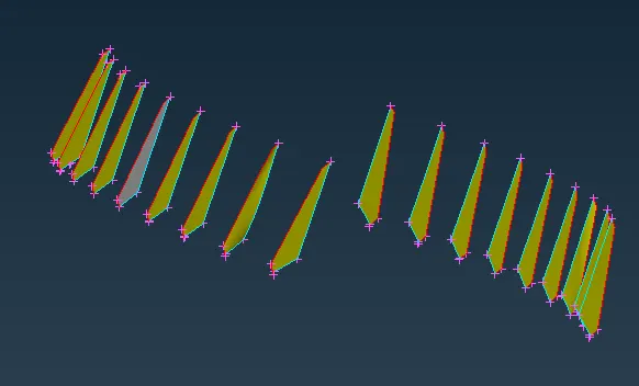
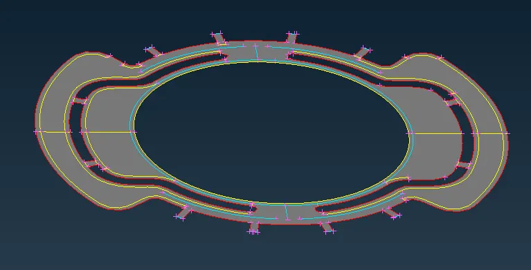
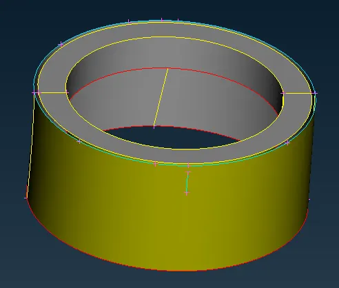
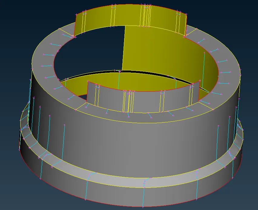
Create a midsurface for teeth in the model. We can use the midcurve option to create a midcurve and project the opposite side.
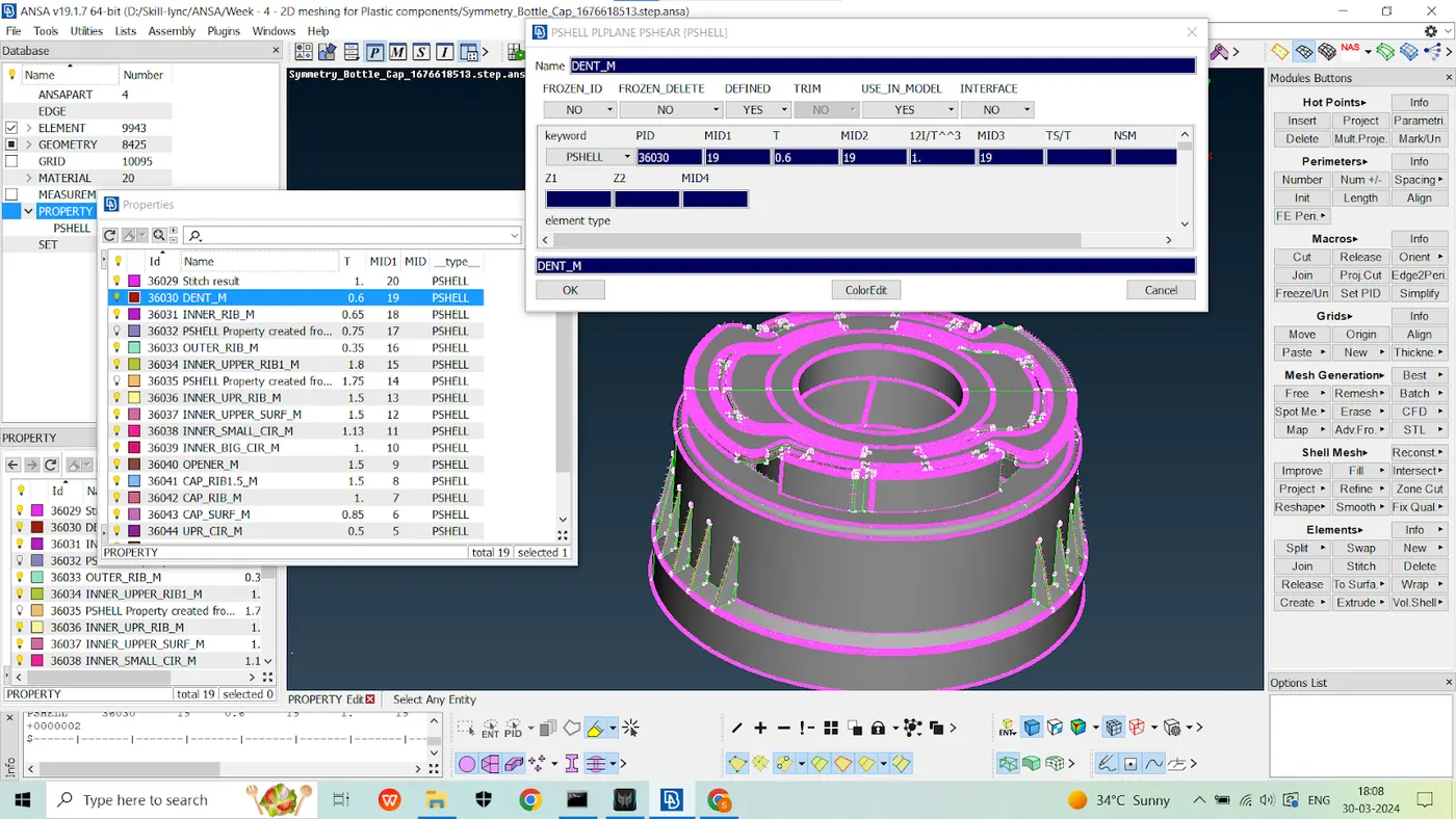
Now, assign the thickness to the midsurfaces. We have some varying thickness surfaces, so we need to create gradual thickness variations beneath one surface.We can easily create property. Choose Property-New-Pshell-Assign Thickness-Assign Name.
After all midsurfaces created use faces - topo to stitch the surfaces together.
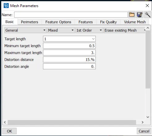
Now we can proceed to mesh the model. First, set the mesh parameters. Give the target element length of 1mm, a minimum length of 0.5mm, and a maximum of 3mm. Select OK.
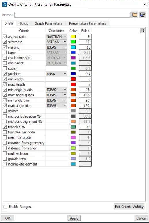
Provide quality criteria for the mesh. Select quality criteria and assign values as shown above. Select the presentation parameters. Select a percentage for each element.Now click OK.
Meshing:
First, select the macros and then the best mesh in the mesh generation. The mesh is now being generated in the macros that have been selected. Follow the same steps for mesh generation.
Now use the reconstruct tool to remesh the existing mesh (mesh-shell mesh-reconstruct).
Now Use the split, paste, and swap options to reduce opposite trias and back-to-back trias in the model's existing mesh (mesh-element-split/swap) (mesh-grids-paste).
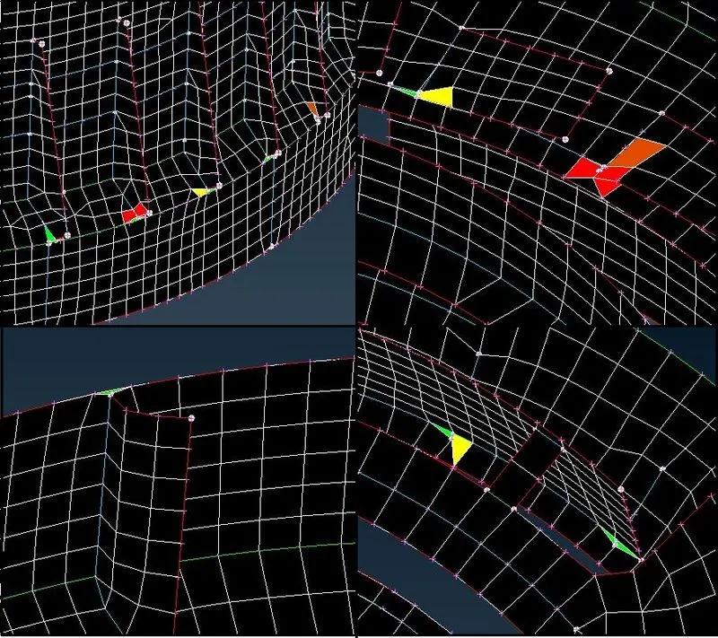
Split is a tool for splitting elements by edges and nodes and moving them forward in a tria.
Paste is the tool used to move the tria backwards by pasting the nodes.
Swap is the tool used to swap the tria to the next element.
Now the mesh has been generated. Check for quality criteria, and correct failed elements using tools such as smooth, reconstruct, fix quality, and move in the mesh module. Finally, a mesh is generated for the given model.
Some elements around the triple cons failed for minimum length and aspect ratio. Those elements are classified as OFF elements.
To see the mesh's thickened solid pattern, select the draw shell as a solid tool in the presentation parameters tab.
Finished component images:
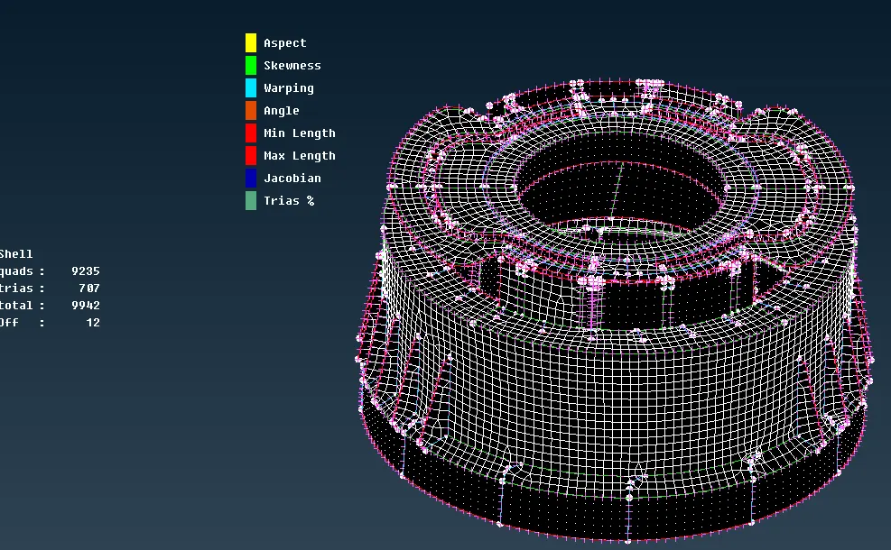
Final Mesh The final shell elements are represented as solid components.
Learning outcomes:
Learned how to use various tools to create midsurfaces, create a surface using a midcurve, and transform the surface pattern in the model.
Project Overview: Midsurfacing and Meshing in Plastic Components
• Understanding the importance of midsurfacing in plastic components with variable thickness.
• Handling the midsurface at complex areas and positioning single, double, and triple cons.
• Assigning thickness properly according to cariable thickness.
• Segments and assigning different thicknesses or average thickness based on feature complexity.
• Handling triple cons in meshing plastic components.
• Splitting different areas for quality mesh.
• Achieving good quality mesh.
• Comparing after mesh with original geometry.
• Helps in understanding midsurfacing of complex geometries like Plastic Bottle Cap..