Week - 4 - 2D meshing for Plastic components
Aim: To extract the midsurface of the plastic components and mesh the midsurface with a minimal number of trias elements with the proper thickness for each part.
Objective:
i) Extract the midsurface of the plastic components
ii) Stitch the surface which is unpasted
iii)Create a Mesh for the component
iv) Check for the Quality criteria
v) Assign the thickness for the component
Extract the CAD model:
Extract the cad Model into the ANSA module in terms of.IGES or ANSA format.
Geometry cleanup:
While we import any geometry data, it will come with errors and geometrical issues.
Surfaces that are not stitched together.
Very small surfaces are squeezed into it.
A duplicate surface is presented and must be removed.
In order to remove that issues and errors, we do geometry cleanup.
An option that is available is Topo, Cut option in Surface, and New faces.
MID-SURFACE:
We can extract mid-surface in two ways
- Manual mid-surfacing
- Automatic mid-surfacing
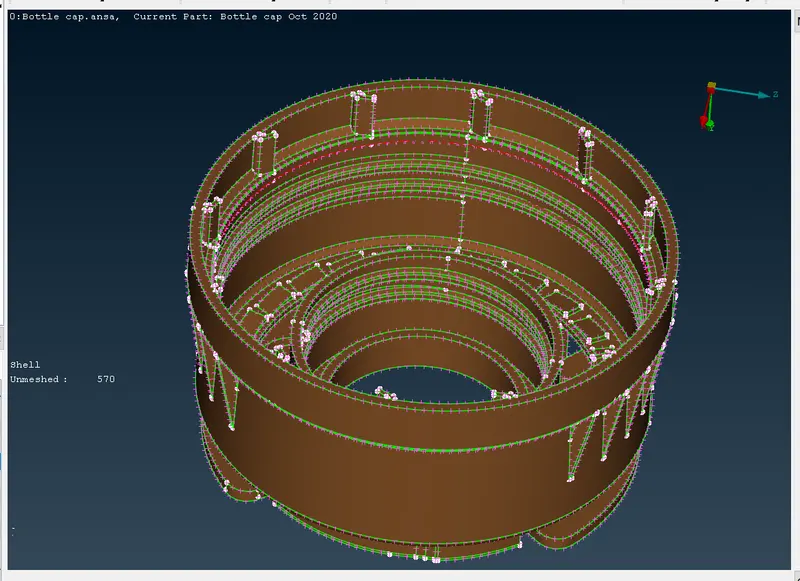
Here for the above component, we choose manual mid-surfacing because the given model is of plastic / cast one, so the thickness is not constant throughout, if we use automatic mid-surfacing and meshing it will not give us the accurate result, the user has to do a lot of changes in the model to repair, so that’s why we choose manual mid-surfacing, in manual mid-surfacing we use the offset option to create the middle surface.
During meshing we have to take care about:
- The feature should be captured properly
- No back-to-back trias
- There should be element connectivity between the elements
- No opposite trias
- No rotational quads
- Quality check to ensure that all elements are within good quality
Quality Criteria:
|
S.No |
Quality Criteria |
Value |
|
1 |
Target/Average length |
1 |
|
2 |
Minimum Length |
0.5 |
|
3 |
Maximum Length |
3 |
|
4 |
Aspect |
3 |
|
5 |
Warpage |
15 |
|
6 |
Skewness |
45 |
|
7 |
Jacobian |
0.7 |
|
8 |
Minimum Quad Angle |
45 |
|
9 |
Maximum Quad Angle |
135 |
|
10 |
Minimum Tria Angle |
30 |
|
11 |
Maximum Tria Angle |
120 |
|
10 |
Tria Percentage |
15 |
Now we have to set the size of the length of the Macros and perimeter
So now we have to select Mesh -> Perimeter/Macros -> Length tool and give 1 because of target element sizes as well as to refine the surface for a good resolution.
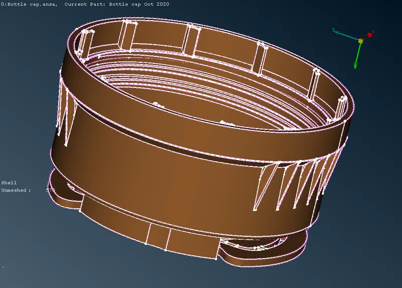
First, measure the thickness of the model to get an idea to extract the midsurface for the macros.
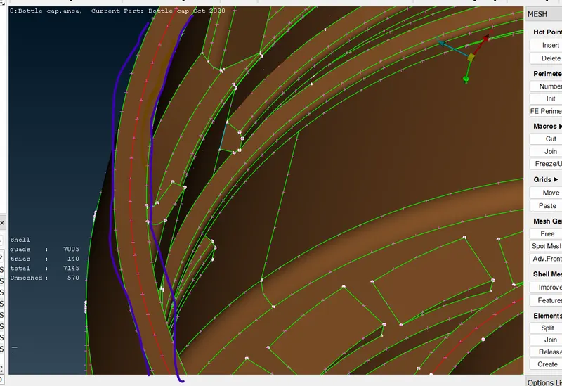
The model has varying thicknesses on some surfaces. Those surfaces are extracted by using the middle tool in the topo module topo-faces-middle-(single or multi). For ribs, we can use both but the surfaces are single. Use middle-single. now select the first surface then click the second surface. Now click "ok" to accept the surface. now the midsurface is generated.
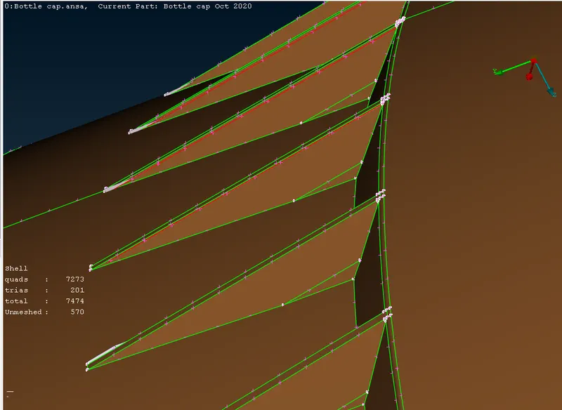
Here we have some threads in the bottle cap. it has a trapezium-shaped surface for those surfaces take the mid curve to get an exact mid-surface topo-curve-middle select the two curves one by one and click ok to get the mid curve. now project the mid curve to midsurface topo-cons-project and now use those curves to create a new surface using topo-faces-new. The midsurface is generated for threads.
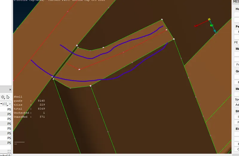
Now transform the ribs around the surface as copy by using Transform-copy-rotate select the midsurface of the rib and select rotate now give X & dx values for an axis of rotation and give the copies and click finish to get ribs. To create an axis of rotation we have to create COG points topo-points-on COG select circle 1 and create a COG point and select a circle 2 above some height use those points for x & dx values.
To extract the midsurface for this component I have used "Curves -> Middle -> Select the Curves"
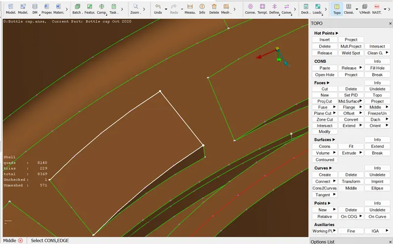
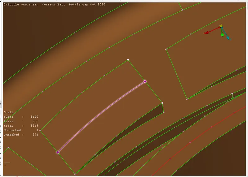
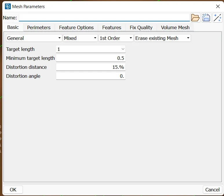
Once extracting the Mid-surface, we have to mesh the model in "Classic mesh", The target element is "1" as assigned.
Min.length is 0.5 and Max.length is 3, then click ok.
Before doing the mesh we have assigned some basic criteria files such as "Mesh Parameters & Quality Criteria"
Now give quality criteria for the mesh. Select Quality criteria and assign values as given in above. select presentation parameters. select elements percentage. Now click ok.
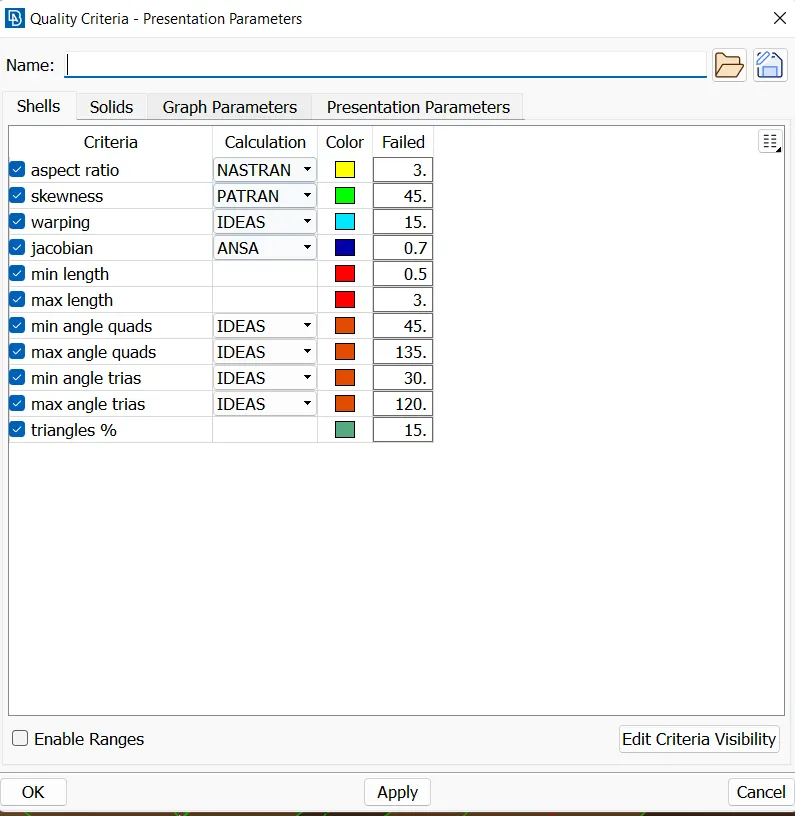
First, select the macros and select the "best mesh" in the mesh generation (mesh-mesh generation-best). now the mesh is generated in the selected macros. follow the same procedure for mesh generation.
Now use reconstruct tool to remesh the existing mesh (mesh-shell mesh-reconstruct).
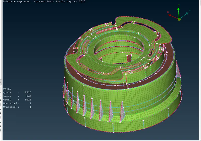
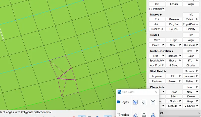
To get a Smooth element in it, we can have some to tools to overcome it.
Now Use the split, paste, and swap options for reducing the opposite trias, and back-to-back trias in the existing mesh in the model (mesh-element-split/swap) (mesh-grids-paste).
- Split- the tool used to split the elements by edges and by nodes and used to move forward the tria.
- Paste- the tool used to move the tria backward by pasting the nodes.
- Swap- the tool used to swap the tria to the next element.
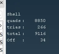
The element which is used to fail will indicate an "OFF" element.
Now Assign the thickness to the element and the surface to show the 2D mesh in an actual thickness.
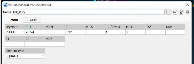
To view the actual thickness of the meshed element, "Quality Criteria -> Parameter Presentation -> 2D shell as Solid".
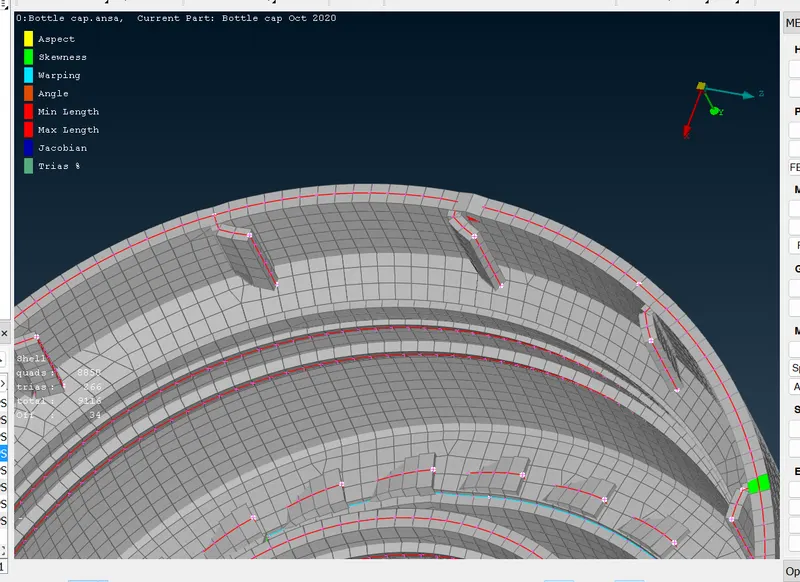
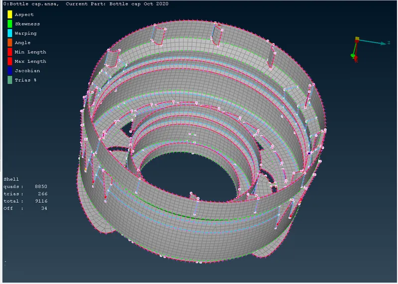
FINAL MESH PART:
Conclusion:
The given Bottle cap model is been meshed with a given quality criteria file here the midsurface is extracted as manually, and assign the thickness to the model.