Week - 4 - 2D meshing for Plastic components
AIM:
To extract the manual midsurface of the given bottle cap, mesh the component using the
given quality parameters and assign thickness.
|
S.No |
Quality Criteria |
Value |
|
1 |
Target/Average length |
1 |
|
2 |
Minimum Length |
0.5 |
|
3 |
Maximum Length |
3 |
|
4 |
Aspect |
3 |
|
5 |
Warpage |
15 |
|
6 |
Skewness |
45 |
|
7 |
Jacobian |
0.7 |
|
8 |
Minimum Quad Angle |
45 |
|
9 |
Maximum Quad Angle |
135 |
|
10 |
Minimum Tria Angle |
30 |
|
11 |
Maximum Tria Angle |
120 |
|
10 |
Tria Percentage |
15 |
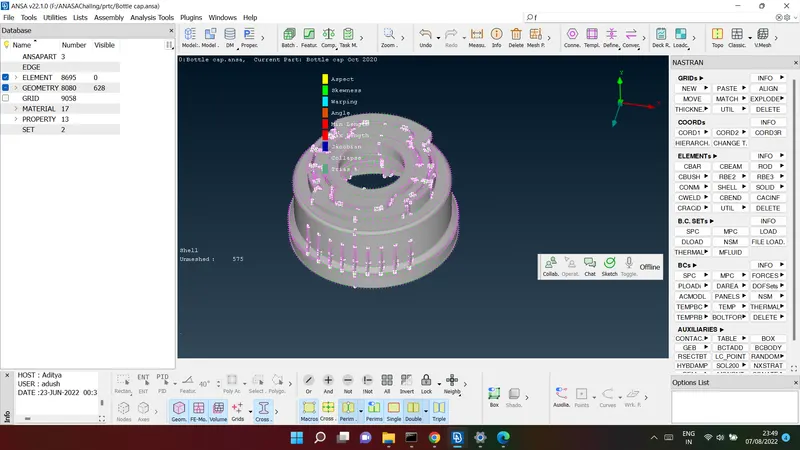
Import the geometry:
file>open>download folder for the geometry >select the module>click on open
PROCEDURE
1. Firstly, before we begin any kind of work on the model, we can go ahead and carry out th
geometry cleanup. That is done via
Checks > Geometry
where we can execute checks of
certain defects that can be selected from the menu and the algorithm looks for said
defects. After detection, we can select all the defects and
right-click > fix to fix them.
topo : chech the cone > if it is single cone (red colour)
topo>topo>select the component
orientation: orient
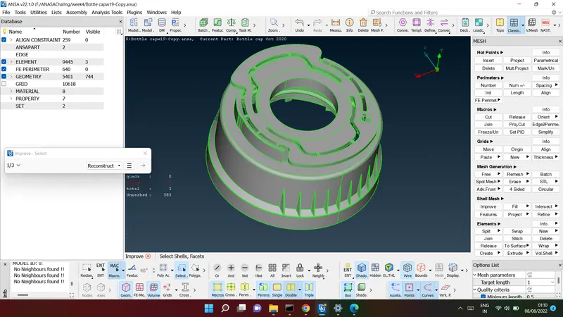
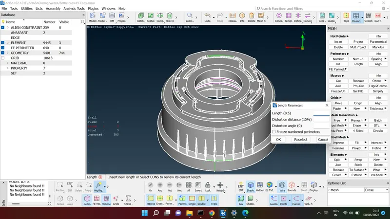
2. After that, we can go ahead and change the cons resolution by accessing the mesh
module and selecting 'length' in the perimeter section.
We will then need to select the whole model and assign a 1 mm length. This improves the resolution of the model as a
whole and at the same time, cater to the target element length requirement for meshing,
which we will be doing later
3. To make it easier, we can break down the model into different views with the help of the
NOT, OR, AND commands to hide certain surfaces.
1)image shows the parameter for element :
Then using the 'store lock' feature, we can save views with surfaces masked. This helps with
ensuring we cater to the complexities of the model. Surfaces are hidden using the 'NOT'
feature and the remaining part of the component can be locked and saved, by clicking the
lock option on the bottom toolbar and then the arrow > 'store lock'
Meshing :
by using casting method :
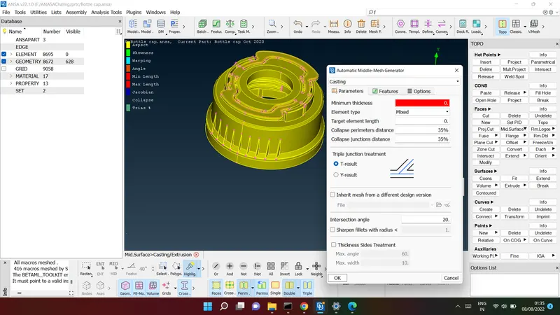
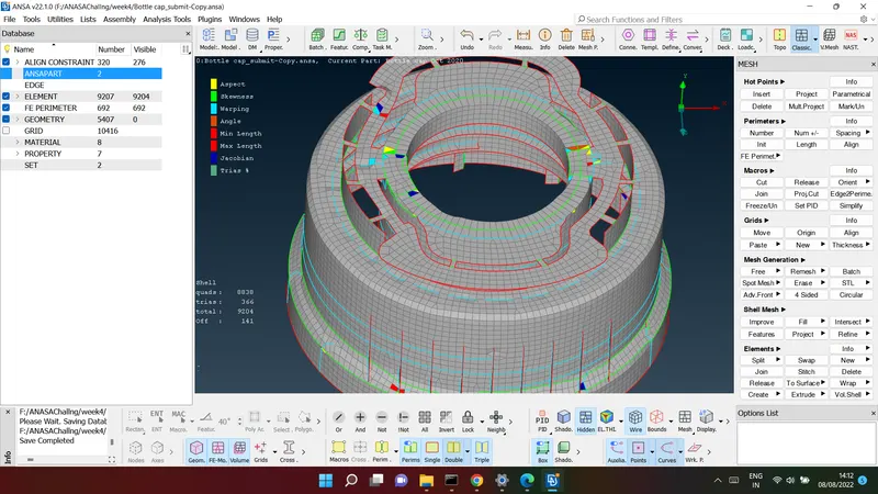
check element quality criteria :
bottom manager > hidden> coloured element shows the different element failure
Assign the thickness:
classic mesh > thickness> assign the thickness> at selected node>
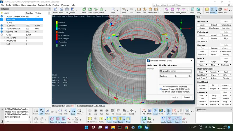
thickness = 1mm
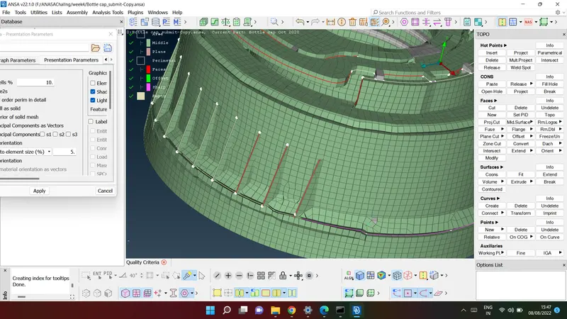
image shows FE Model with shell as solid
LEARNING OUTCOMES
1. Learnt to make use of the middle tool - a third alternative to midsurface creation.
2. Also learnt the transform > rotate option, to form copies of the same surface around an
axis.
3. Was able to familiarize with the intersect, extend and project tools which were required
for this component.
4. Also learnt to make use of curves to generate surfaces, be it through manually created
curves as well as curves generated with the help of cons.
RESULT
The given bottle cap component was meshed as per required quality criteria, after having
carried out topology cleanup and generated midsurfaces for each of its surfaces and
thickness was assigned to each of them.